Document No. 129-400
Installation Instructions
October 2, 2009
Siemens Industry, Inc.
Page 3 of 5
Electrical Connection
SQM5… actuators are equipped with two removable
conduit connection plates located on the upper corner
of the gear housing. Each plate is provided with two
threaded connections for 1/2-inch NPSM conduit
connectors. The use of flexible 14 gauge or smaller
stranded wire is recommended.
NOTE: SQM5… Actuators require a single-source,
single-phase power supply.
Grounding
To avoid electro-magnetic interference, SQM5…
actuators must be grounded. The ground screw is
located to the right of the AUTO/MAN switch (below
the shaft release button).
Disconnect the circuit board wire marked 51
during high voltage testing. Reconnect it to
the grounding terminal after the test.
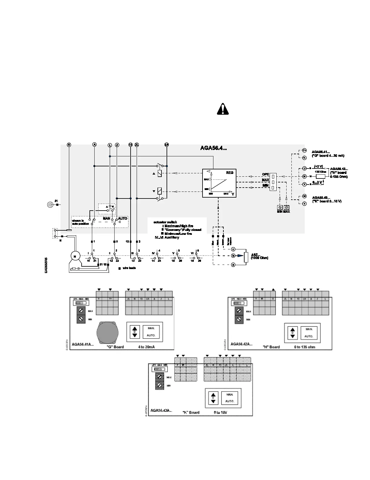
Figure 4. Basic Functional Diagram of AGA56.4…
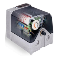
Figure 5. AGA56.41/42/43… Terminal and Trim Potentiometer Boards.
 Loading...