Do you have a question about the Siemens SQN72 Series and is the answer not in the manual?
Describes the use of SQN72/SQN73 actuators in HVAC systems for air and gas dampers.
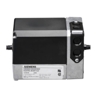
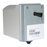
Lists principal characteristics of the actuators including housing, terminals, and internal components.
Covers prevention of personal injury, property damage, and environmental harm.
Notes on preventing electric shock, ensuring touch protection, and avoiding ESD.
Advice on selecting the correct actuator version based on torque and mechanical design.
Compliance with regulations, avoiding solar radiation, and secure connections.
Ensuring IP54 rating is maintained through proper installation of drive shaft bearing.
Recommendations for shaft connections and managing bearing loads.
Compliance with wiring regulations, strain relief, and terminal protection.
Details on applied directives (Low Voltage, EMC) and relevant standards.
Information on expected service life based on start cycles and replacement criteria.
Guidance on unit replacement, function assignment, and proper waste management.
Materials, synchronous motor, reduction gear, camshaft, and switch sections.
Description of the synchronous motor and its disengageable coupling.
Cam disks for adjustment, scales, and internal position display.
Details on the maintenance-free gear and the drive shaft mounting.
Actuator suitability for potentiometer integration and separate ordering.
Mains voltage, frequency, motor, consumption, angle, position, and protection class.
IP54 details, fuse, cable entry, strain relief, and connection terminals.
Ferrules, direction of rotation, torque, and running times.
Number of switches, actuation method via camshaft, and fine adjustment.
Permissible current load per circuit and inductive load notes.
Temperature and humidity ranges for storage, transport, and operation.
Vibration and shock test standards applied to the actuator.
Motor-driven camshaft actuating switches, with optional electronic modules.
Explains diagram start position, end switch state, and general notes.
Circuit diagram and program sequence for LME22 in 2-stage or modulating mode.
Circuit diagram and program sequence for LOA/LMO controllers.
Circuit diagram and program sequence for LMO39 in 2-stage mode.
Circuit diagram and program sequence for LFL/LGK16/LAL/LOK16.
Circuit diagram and program sequence for LME22, type D.
Circuit diagram and program sequence for LAL/LFL/LGK16/LOK16, type E.
Measured dimensions of the actuator housing in millimeters.
Visuals and specifications for shaft side view, cross-section, and numbering.
The Siemens SQN72... and SQN73... series are electromotoric actuators designed for precise positioning and driving of air and gas dampers in oil and gas burners of small to medium heat capacity. They also facilitate load-dependent control of fuel and combustion air. These actuators are primarily intended for original equipment manufacturers (OEMs) for integration into their products.
The SQN72/SQN73 actuators operate by a synchronous motor driving a camshaft via a gear train. This camshaft, in turn, actuates end switches and auxiliary switches. The switching position of each end switch and auxiliary switch can be adjusted by an assigned cam disk within the running range of the actuator. Certain actuator versions incorporate electronic switching modules that provide additional functions in conjunction with the end switches, auxiliary switches, and external units such as controllers.
The controlling elements are managed based on the current burner load. This can be achieved in several ways:
The actuators are designed to offer load-dependent control of the amount of fuel and combustion air, ensuring efficient burner operation.
| Brand | Siemens |
|---|---|
| Model | SQN72 Series |
| Category | Controller |
| Language | English |