Siemens Building Technologies CM1N4573E / 06.2001
Landis & Staefa Division 7/8
Connection terminals
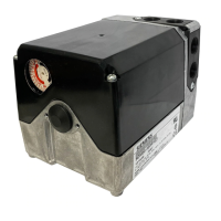
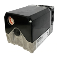
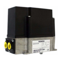
SQS65….
GYRMU
G0
4573G03
G, G0 Operating voltage AC 24 V
G System potential (SP) corresponds to LS on SQS65.2
G0 System neutral (SN) corresponds to NS on SQS65.2
Signal inputs
Y SQS65, SQS65.5 DC 0...10 V
SQS65.2 DC 2...10 V
RSQS65, SQS65.2, SQS65.50 ...1000 ohms
M Measuring neutral
USignal output
SQS65, SQS65.2, SQS65.5 DC 0...10 V
All connection options are illustrated in the connection diagrams. How many and which
of these are used, depends on the system.
If a device is connected to terminal R, the factory-fitted bridge across R – Monthe
printed circuit board must be cut through.
SP
SN
Y(1,2,3)
RM MR G0Y
GY(Y')RM U
GO
AC 24 V
N1 R1 F1 K1P1
Y1
4573A01
G
SP
SN
LS
NS Y (1,3)
RM
GY
G0
RM
MR
U
G0
Y
G
4573A02
AC 24 V
N1 R1 F1 P1 K1
Y1
Equipment
F1 Frost detector
K1 On/off switch
N1 CLASSIC controller
P1 Position indicator
R1 Position transmitter
K1 On/off switch
N1CLASSIC controller
P1Position indicator
R1Position transmitter
Y1Actuator
Connection
diagrams
Note
SQS65, SQS65.5
(AC 24 V, DC 0 ...10 V)
SQS65.2
(AC 24 V, DC 2 ...10 V)

 Loading...