Technical Instructions Flowrite™ 599 Series SAX Electronic Valve Actuator
Document Number 155-507 Non-spring Return, 24 Vac 3-position (Floating) Control
April 5, 2012
Page 6 Siemens Industry, Inc.
Mounting and
Installation
Indoor or Outdoor Use
1
1) Only in connection with Weather Shield ASK39.1 for NEMA 3R protection.
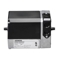
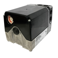
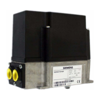
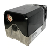
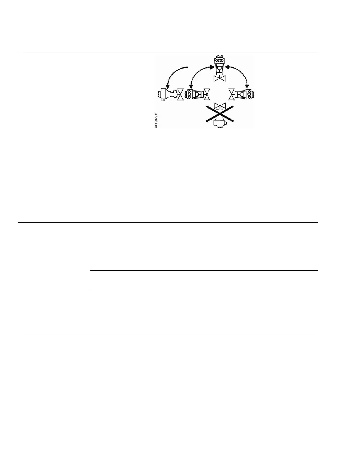
Figure 2. Acceptable Mounting Positions.
The vertical position is the recommended position for mounting.
Figure 2 shows the
acceptable mounting positions.
Allow 8 inches (200 mm) above and on the wiring side of the actuator, and four inches
(100 mm) on all other sides of the actuator. This service envelope is the minimum
space required to access and service the actuator. See Dimensions for actuator
dimensions and the recommended service envelope.
Start-Up
Check the wiring for proper connections.
NOTE: The valve body assembly determines the complete assembly action.
Normally Closed Valve
Y1 control signal extends the actuator (0 to 1): Valve opens.
Y2 control signal retracts the actuator (1 to 0): Valve closes.
Normally Open Valve
Y1 control signal extends the actuator (0 to 1): Valve closes.
Y2 control signal retracts the actuator (1 to 0): Valve opens.
Three-Way Valve
Y1 control signal extends the actuator (0 to 1): Valve opens between Ports A and AB
(through port).
Y2 control signal retracts the actuator (1 to 0): Valve opens between Ports B and AB
(bypass port)
Wiring
Do not use auto transformers. Use earth ground isolating step-down Class 2 power
supplies.
Determine supply transformer rating by summing total VA of all actuators used.
The maximum rating for Class 2 step-down transformer is 100 VA. It is recommended
that no more than 10 actuators are powered by one transformer.
 Loading...