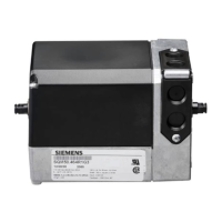
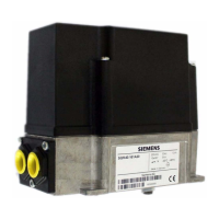
Flowrite™ 599 Series SAX Electronic Valve Actuator Technical Instructions
Non-spring Return, 24 Vac 3-position (Floating) Control Document Number 155-507
April 5, 2012
Siemens Industry, Inc. Page 7
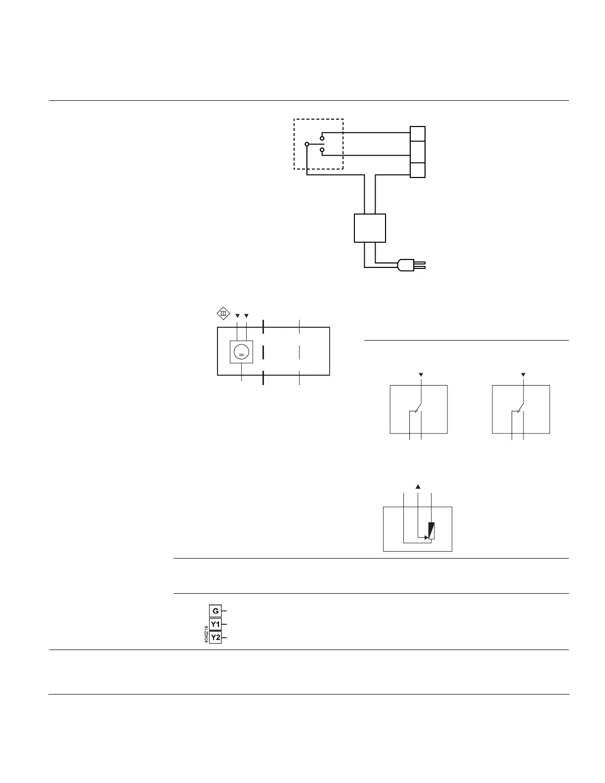
Wiring Diagrams
EA0744R1
EARTH GROUND
ISOLATING CLASS 2
TRANSFORMER FOR
24 Vac POWER
120 Vac
Y2
Y1
G
NEUT
CONTROLLER
24
Vac
Figure 3.
Accessories
VE0357R1
AB
Y1 Y2
G
24 Vac
M
A and/or B
1x ASC10.51
Auxiliary Switch
1x ASC10.51
Auxiliary Switch
VE0356R1
S1
S2S3
24 Vac to 230V / 6 (3) A
VE0356R1
S1
S2S3
24 Vac to 230V / 6 (3) A
Figure 4. Wiring Designations.
or 1 x ASZ7.5/..
Potentiometer
VE0360R1
P1 P2 P3
SELV/PELV 1000 Ω
0 200 Ω
0 135 Ω
100%
0%
The diagram shows all possible connections. The application determines which
connections are used.
24 Vac/Vdc, 3-Position
System potential (SP)
Wiring Terminals
Positioning signal (actuator’s stem extends)
Positioning signal (actuator’s stem retracts)
Check that the wires are connected correctly and attached securely.
Troubleshooting
Check for adequate power supply.
 Loading...