Siemens Industry, Inc.
Building Technologies Division
P/N 315-034170-137
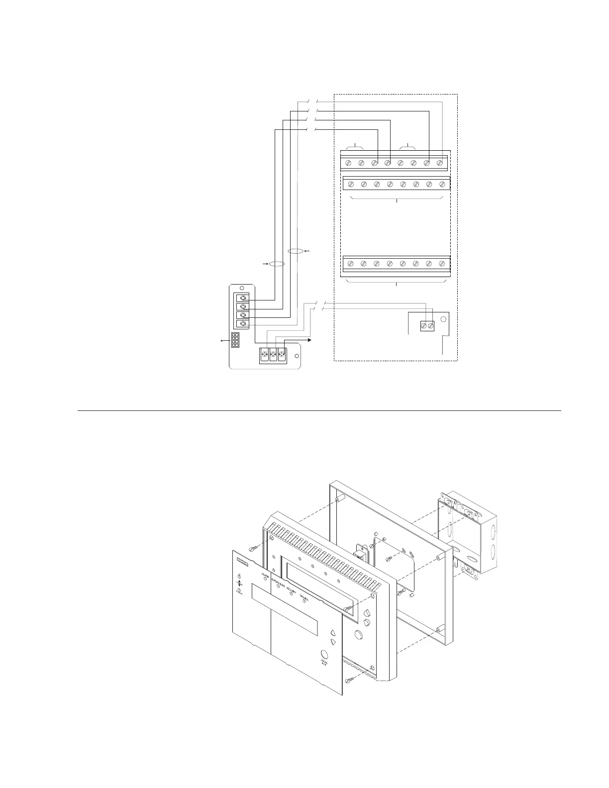
The wiring diagram in Figure 6 shows the connections from the SSD to the NIC-C
and PSC-12. Refer to the NIC-C Installation Instructions, P/N 315-033240 and the
PSC-12 Installation Instructions, P/N 315-033060 for additional wiring information.
SSD-TB
PAIR A
EARTH
GROUND
CABLE
TO SSD
MAIN
PAIR B
A+
A–
B–
B+
P1
PSC-12
1
+
–
2
TB3
12345678
910111213141516
17 18 19 20 21 22 23 24
DO NOT USE
DO NOT USE
DO NOT USE DO NOT USE
ONE SLOT OF CC-5
NIC-C
+
E
–
TB1
TB2
Figure 6
Wiring The SSD
INSTALLATION The SSD mounts directly onto a (user supplied) double gang or 4 inch switchbox.
Refer to Figure 7.
DOUBLE GANG BOX
3 1/2-INCHES DEEP
( A 4-INCH SQUARE BOX
2 1/8-INCHES DEEP
CAN ALSO BE USED)
MOUNTING PLATE
SSD ASSEMBLY
OVERLAY
Figure 7
Installing The SSD
NOTES:
1. Compatible wire size:
14 - 18 AWG
2. No EOLR required. S1-1 has
to be in the ON position if
the SSD is at the end of a
Style 4 network.
3. Use twisted pair (Style 4/7)
or twisted shielded pair
(Style 4 only).
4. Terminate shield at one end
only.
5. Power Limited to NFPA 70
per NEC 760.
6. All wiring is power limited
and supervised.
7. For Style 7 networks the
SSD must be installed in
between two NIC-Cs.