TPS- Installation Instructions for:
Lighting Panelboards Revise P (RP)
If model number includes W option suffix, additional
instructions follow:
The following instructions are for the installation of the
Siemens TPS and L SPD modules in Siemens Revised P
(RP) lighting panelboards.
Be aware of differences between the Revised P
and Original P panelboards. SPDs for Original P
and Revised P are not interchangeable. Original
P panelboards use TPS or L SPDs, whereas
Revised P panelboards use TPS or L SPDs or
the new TPS or L SPDs..
To determine if a customer has a Revised P panel
– look at the part number of the interior. If the
part number ends with “N” or “T” then it is a
Revised P. If it does not end in either “N” or
“T” then it is an Original P panel. For example:
PEMCA is an Original P panel and
PEMCAT is a Revised P panel. If it is a
Revised P panel ending in “N” – then there is
no Subfeed space and no place for an SPD to be
installed internally. A different SPD like the new
Bolthshield BSPD product line can be an option
for the Revised P panel ending in “N” because
it mounts in a unit space.
Item Description Qty. Torque
TPS
TPS Mounting Plate
#- Hex Screw w/captive washer in-lb
#- Hex Thread Rolling Screw in-lb
TPS Phase Tabs (part of TPS unit) * or
#/- Hex Screw w/captive washer * or in-lb
Neutral Lug Wire Connection N/A in-lb
” # AWG White Neutral Conductor
*only 2 tabs for single phase modules
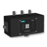
Figure : Revised P Panel
1
2
3
4
5
6
7
8
Figure : Revised P Panel Phase Tab Detail
Step ) Lock off all power supplying this equipment before
working on it.
Step ) Attach TPS Mounting Plates (Item , Places) to
TPS using - SEM screws with captive lock washers
(Item ). The mounting plates should be attached to the
TPS with the offset oriented towards the top of the unit.
Torque Screws to values listed.
Step ) Position the TPS unit (item ) on the panel base rail
so that the TPS Phase tabs (Item ) extend beneath the Bus
Tabs on RP Panel. Attached TPS Phase Tabs to Panel Bus
using #/- Hex SEM Screws (Item ). Do not Torque at
this time.
Step ) Connect the TPS unit to the base rail using four ()
of the #- Hex Thread Rolling screws (item ).
Step ) If present, connect TPS Neutral Connection Lug
(Item ) to Panel Neutral using AWG minimum wire.
For best SPD performance, trim wire as required to provide
shortest possible route between TPS Neutral connection
and Panel Neutral Connection. Route wire as straight as
possible and use gentle radius on any bends. Do not kink
wire. Prevent wire from encroaching breaker locations.
Neutral Connection is not applicable on Delta systems.
Step ) Torque all connections to the values as specified on
the installation and maintenance instruction label affixed to
the rear of the dead front.
Table : Content for Installation in Lighting Panelboards
Revised P
TPS Surge Protection Devices | Installation Guide / User Manual Installation Guide / User Manual | TPS- Surge Protection Device
Figure : SPLIT
Hots, Neu, Grnd
Figure : WYE
Hots, Neu, Grnd
Figure : HI-LEG DELTA
(B High)
Hots, (B HIGH),
Neu, Grnd
Figure : DELTA &
HRG WYE
Hots, Grnd
Table : Model Number Catalog Logic
Voltage Code Surge Current Rating Options ( Alpha numeric Character)
A = /V ,Ø, W (Figure ) = kA per phase X = Surge Counter (Standard)
B = /V, Ø, W (Figure ) = kA per phase = Standard Configuration (Default)
C = /V, Ø, W (Figure ) = kA per phase W = Terminal Lug
W = /V, Ø, W (Figure ) = kA per phase = Standard Configuration
(Default)
D = V, 3Ø, W (Figure ) = kA per phase B = Busway Application
E = /V, Ø, W (Figure ) = kA per phase M = MCC Application
F = V, Ø, W (Figure ) = kA per phase = Type SPD
(Default) Includes UL EMI/RFI Filters
G = V, Ø, W (Figure )* = Type SPD
K = /V, Ø, W (Figure )
L = /V, Ø, W (Figure )
S = /V, Ø, W (Figure )
T = /V, Ø, W (Figure )
*Not avilable in 300, 400 or 500kA versions
Catalog # TPS o oo X ooo
Example: TPSCX =
SPD for a /V panelboard with a surge current capacity of
kA per phase and a surge counter option.
When an option is not selected, include a zero () in the field.
Example: TPSCLX =
SPD for a /V panelboard with a surge current capacity of
kA per phase and a surge counter option.
When an option is not selected, include a zero () in the field.
TPS SPD for “RP”, P, P Lighting Panelboards, MCC and Busway
General Suppressor Series
Voltage Code Surge Current Rating Options ( Alpha numeric Character)
A = /V ,Ø, W (Figure ) = kA per phase X = Surge Counter (Standard)
B = /V, Ø, W (Figure ) = kA per phase = Standard Configuration (Default)
C = /V, Ø, W (Figure ) = kA per phase W = Terminal Lug
W = /V, Ø, W (Figure ) = kA per phase = Standard Configuration
(Default)
E = /V, Ø, W (Figure ) = kA per phase B = Busway Application
K = /V, Ø, W (Figure ) M = MCC Application
L = /V, Ø, W (Figure )* = Type SPD
(Default) Includes UL EMI/RFI Filters
S = /V, Ø, W (Figure ) = Type SPD
T = /V, Ø, W (Figure )
*Not avilable in 450, 550 or 750kA versions
Catalog #
TPS o L oo X ooo
TPS L Mode SPD for “RP”, P, P Lighting Panelboards, MCC and Busway
General Suppressor Series
 Loading...