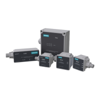
This document is an installation, operation, and maintenance manual for Siemens Surge Protection Devices (SPDs), specifically the FSPD, TPS4 03, TPS4 09, and TPS4 11 series. These devices are designed to protect electrical systems and equipment from voltage surges.
Function Description
Surge Protection Devices (SPDs) are designed to limit transient overvoltages and divert surge currents to ground, thereby protecting electrical equipment from damage. The FSPD, TPS4 03, TPS4 09, and TPS4 11 series offer various levels of surge current protection and are suitable for different applications within power distribution systems. They are equipped with internal overload protection elements and have demonstrated high Short Circuit Current Ratings (SCCRs).
Important Technical Specifications
FSPD Series:
The FSPD series offers different surge current capacities:
- FSPD036: 36 kA
- FSPD060: 60 kA
- FSPD100: 100 kA
- FSPD140: 140 kA
The FSPD series is tested and qualified as a Type 2 SPD per UL 1449 4th Ed.
TPS4 03 Series:
- Surge Current: 50 kA per phase.
- Voltage Codes (Examples):
- A = 120/240 V, 1Ø, 3W
- B = 120/240 V, 3Ø, 4W
- C = 120/208 V, 3Ø, 4W
- E = 277/480 V, 3Ø, 4W
- F = 480 V, 3Ø, 3W
- G = 600 V, 3Ø, 3W
- Options:
- 0 = No Dry Contact & No Audible Alarm
- N = N-G Protection (Standard)
The TPS4 03 series is tested and qualified as a Type 1 SPD, allowing installation on the Line Side of the service overcurrent device or in UL Type 2 applications.
TPS4 09 Series:
- Surge Current: 130 kA per phase.
- Voltage Codes (Examples): Similar to TPS4 03, covering a wide range of single-phase and three-phase systems (e.g., 120/240 V, 277/480 V, 600 V).
- Options:
- D = Dry Contact & Audible Alarm (Standard)
- E = Extended indicator light
- I = Internal mounting in P1, P2 panels
The TPS4 09 series is tested and qualified as a Type 1 SPD, allowing installation on the Line Side of the service overcurrent device or in UL Type 2 applications.
TPS4 11 Series:
- Surge Current: Available in 100 kA, 150 kA, 200 kA, and 250 kA per phase.
- Voltage Codes (Examples): Similar to TPS4 03 and TPS4 09, covering various single-phase and three-phase systems.
- Options:
- -2 = Type 2 SPD (Default), includes UL 1283 EMI/RFI Filters.
- 0 = Type 1 SPD (Consult Factory Prior to Ordering).
- D = Dry Contacts & Audible Alarm (Standard).
The TPS4 11 series is tested and qualified as both Type 1 and Type 2 SPD.
General Specifications:
- Enclosure: Standard units use a NEMA 4X enclosure. Flush-mount kits are available as options.
- Operating Temperature Range: -40°C (-40°F) to +85°C (+185°F).
- Relative Humidity: 0% to 95% (noncondensing).
- Short Circuit Current Ratings (SCCRs): Demonstrated 200kA.
- Dry Contact Specifications (if applicable):
- Designed for low voltage or control signals only.
- Maximum switching current: 2A.
- Maximum switching voltage: 240Vac.
- Wiring: Three 21" 18 AWG wires (Yellow/White is Common, Black is Normally Open, Brown is Normally Closed).
Usage Features
Installation Flexibility:
- Line Side vs. Load Side: Type 1 SPDs (TPS4 03, TPS4 09, TPS4 11) can be installed on the line side of the service overcurrent device or in UL Type 2 applications. Type 2 SPDs (FSPD, TPS4 11 default) are typically installed on the load side of the main overcurrent device for easier maintenance.
- Lead Lengths: SPDs should be located as close as possible to the circuit with the shortest and straightest leads to minimize parasitic losses. Leads should be gently twisted together if longer runs are unavoidable.
- Circuit Breaker Connection: When connected on the load side, a 20-30A circuit breaker is suggested for disconnect and short circuit protection.
- Retrofit into Existing Panels: Instructions are provided for retrofitting into panels without available breaker positions, potentially using a ten-foot tap rule with a safety switch fused to 30A.
Diagnostic Indicators:
- LED Operation: Each SPD includes one green LED per phase. A green LED indicates complete protection. If an MOV stack fails, the corresponding LED will extinguish.
- Audible Alarm: An audible alarm will sound upon suppression element failure (if equipped). The alarm can be silenced by removing power to the SPD.
- Dry Contacts: Available on some models, these contacts change state during inoperative conditions (including loss of power), allowing remote monitoring of the SPD's status.
Safety Features:
- Hazardous Voltage Warning: Emphasizes the importance of qualified electricians, de-energizing the system before installation/service, and using appropriate Personal Protection Equipment (PPE).
- Bonding and Grounding: Strict adherence to NEC® guidelines for neutral bonding to ground is critical to prevent abnormally high voltages and SPD failure. Incorrect bonding voids the warranty.
- Ungrounded Systems Caution: Ungrounded systems are inherently unstable and can produce high line-to-ground voltages, potentially exceeding SPD ratings. SPDs specifically designed for ungrounded systems should be used in such cases.
- No Hi-Pot Testing: SPDs must be disconnected from the power source before any high-potential insulation testing or other tests that subject suppression components to voltages exceeding their rated Maximum Continuous Operating Voltage (MCOV). Failure to do so will damage the SPD and void the warranty.
Maintenance Features
Minimal Maintenance:
- SPDs require minimal maintenance.
- Periodic Inspection: Regular inspection of diagnostic indicators (LEDs, audible alarms) is recommended to ensure proper operation.
- Cleanliness: Keeping the SPD clean as appropriate is also recommended.
Troubleshooting and Service:
- In case of an audible alarm cycling immediately after energizing, de-energize the unit and contact Siemens Technical Support.
- For any service-related issues, users are directed to contact Technical Support.