TPS Installation Instructions for:
Power Panelboards (P, P) and Distribution
Switchboards
Full Catalog ID Replacement Instructions
The following general observations should be noted
concerning field replacement of TPS- assemblies with
TPS assemblies.
For Panelboard (Power Panel/PP) & Distribution
Switchboards, TPS- may be replaced with a TPS- using
the following procedure:
Step ) Lock OFF all power suppling panel.
Step ) Remove gutter covers from panel.
Step ) Remove entire dead-front from panel.
Step ) Disconnect line side wires (Phase and Neutral) from
TPS- disconnect switch.
Step ) Remove TPS- enclosure by removing mounting
screws reached via access holes in back plane of enclosure.
Step ) Re-route phase wires to opposite side of panel.
Step ) Re-route neutral wire to opposite side of panel if open
lug position is available.
• If lug position is not available, leave neutral lug in its
original position in panel and run a longer neutral wire.
Step ) Reverse steps to install TPS-.
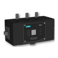
Module Only Replacement Instructions
Figure : P, P and Front Connected Distribution
Switchboards
NOTE: TPS4 internal module may be replaced provided all power sources
are locked out.
NOTE: Following replacement of a TPS4 internal module, the LCD display
will now reflect the new serial number for that module.
Step ) Lock OFF all power supplying this equipment before
working on it. Open unit door and turn the internal
disconnect to the OFF position.
Step ) Un-bolt the phase wire compression lugs from the
phase connectors on the TPS module.
Step ) If present, remove neutral wire from mechanical lug
on side of TPS module.
Step ) Remove the TPS module from back panel by
removing the () Hex Head mounting screws located at
corners of the TPS unit.
Step ) Remove () mounting brackets from bottom of TPS
module. Note orientation of bracket. Each mounting bracket
is attached via () hex head screws ( total).
Step ) Replace unit with the new TPS module.
Step ) Reattach mounting brackets to bottom of TPS
module. Torque screws to . in-lbs.
Step ) Re-install TPS module onto back plate using the
original () hex head screws. Torque to . in-lbs.
Step ) Reattach line wire compression lugs to phase
connections on TPS module. Torque to in-lbs.
Step ) If present, reattach neutral wire to mechanical lug
on side of TPS module. Torque to in-lbs.
Step ) Turn the internal disconnect back to the ON position.
Step ) Close all doors before reenergizing.
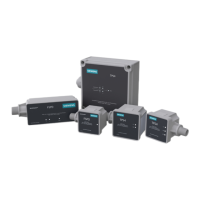
The following instructions are for the replacement of Siemens
TPS SPD module in Siemens TPS unit.
TPS Surge Protection Devices | Installation Guide / User Manual
Installation Guide / User Manual | TPS Surge Protection Devices
Figure : SPLIT
Hots, Neu, Grnd
Figure : WYE
Hots, Neu, Grnd
Figure : HI-LEG DELTA
(B High)
Hots, (B HIGH),
Neu, Grnd
Figure : DELTA &
HRG WYE
Hots, Grnd
Table : Model Number Catalog Logic
Voltage Code Surge Current Rating Options
( Alpha numeric Character)
A = /V ,Ø, W (Figure ) = kA per phase X = Surge Counter (Standard)
B = /V, Ø, W (Figure ) = kA per phase = Type SPD
C = /V, Ø, W (Figure ) = kA per phase
(Default) Includes UL EMI/RFI Filters
W = /V, Ø, W (Figure ) = kA per phase = Type SPD
D = V, 3Ø, W (Figure ) = kA per phase
E = /V, Ø, W (Figure ) = kA per phase
F = V, Ø, W (Figure ) = kA per phase
G = V, Ø, W (Figure )*
K = /V, Ø, W (Figure )
L = /V, Ø, W (Figure )
S = /V, Ø, W (Figure )
T = /V, Ø, W (Figure )
*Not avilable in 300, 400 or 500kA versions
Catalog # TPS o oo X o
Example: TPSCX =
SPD for a /V panelboard with a surge current capacity of
kA per phase and Type SPD.
Example: TPSCLX =
SPD for a /V panelboard with a surge current capacity of
kA per phase and Type SPD.
TPS SPD for P, P Power Panelboards and Distribution Switchboards
General Suppressor Series
Voltage Code Surge Current Rating Options ( Alpha numeric Character)
A = /V ,Ø, W (Figure ) = kA per phase X = Surge Counter (Standard)
B = /V, Ø, W (Figure ) = kA per phase = Type SPD
C = /V, Ø, W (Figure ) = kA per phase
(Default) Includes UL EMI/RFI Filters
W = /V, Ø, W (Figure ) = kA per phase = Type SPD
E = /V, Ø, W (Figure ) = kA per phase
K = /V, Ø, W (Figure )
L = /V, Ø, W (Figure )*
S = /V, Ø, W (Figure )
T = /V, Ø, W (Figure )
*Not avilable in 450, 550 or 750kA versions
Catalog #
TPS o L oo X o
TPS L Mode SPD for P, P Power Panelboards and Distribution Switchboards
General Suppressor Series
 Loading...