7ML19985HX62 XCT-8 Sanitary Transducer– INSTRUCTION MANUAL Page EN-5
English
Mounting
Mount the transducer so that it is above the maximum material level by more than the
blanking value to ensure that accurate results are achieved. Refer to the associated
transceiver manual for information on setting the blanking value.
The transducer must be mounted so that the axis of transmission is perpendicular to the
measured surface to get the most reliable signal. See
Transducer Placement
on page 7
for an example.
Always use an isolation gasket
(customer supplied) when
mounting the XCT-8. This gasket
reduces ultrasonic energy
coupling to the mounting
hardware.
Transducer must be mounted on a
4” ferrule. Do not mount by conduit
threads.
After applying the sanitary clamp,
adjust the clamp as required to
seal the transducer to the vessel
ferrule. Do not over tighten the
mounting. Hand tightening of the
mounting hardware is sufficient.
• sanitary clamp – Siemens
Milltronics 7ML1830-1BR
May be substituted with a
clamp meeting these
specifications:
• 4” single hinge, sanitary clamp
• 4.820” interior diameter
•300 psi rated
• sanitary ferrule – customer supplied
Refer to the associated transceiver manual for details on blanking, standpipe length, and
wiring.
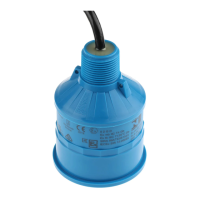
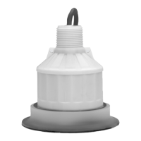
XCT - 8 transducer
isolating gasket
(customer
supplied)
sanitary clamp
4” sanitary ferrule
 Loading...