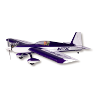
❑ 6) From the kit contents locate two nylon control horns, four
M2 x 3/4” Phillips Head bolts and two wire aileron pushrods
(threaded at one end, “Z”-bend at the other end).
You will also need the aileron servo output arms that you intend to
use. We like using the 4-arm type, choosing the arm with the
longest length. You will likely have to use a small drill to open the
holes in the servo arm in order to accept the .070” dia. pushrod
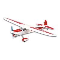
wire. Slip the “Z”-bend end of the wire pushrod into the outer hole
in the output arm and press the output arm onto the servo with the
arm facing 90
O
down into the fairing molding on the servo tray, as
shown (this is the ideal “neutral” position for the servo with the
radio system on). Thread the metal control link onto the aileron
pushrod about halfway, allowing an equal amount of adjustment in
either direction.
With the servos accessible, now is the time to check their
movement and centering with your radio system. Connect the
servo leads to the Y-harness and plug it into the correct aileron
receptacle in your receiver. Connect the battery and turn the
system on. First check for the correct direction of travel. Reverse
the servo direction on your transmitter if necessary. Next, check
the centering of the servo arms, with the trim lever in neutral.
Remember that the output arm should be facing directly into the
molded fairing in the servo tray, at 90
O
to the servo. Take off and
reposition the output arm as needed to achieve this. With these
two issues addressed, install and tighten the servo output arm
screws in both servos. Carefully re-install the servo and tray back
into the aileron servo bay opening in the wing panel and secure it
in place with four #2 x 5/16” Phillips/Washer Head screws. Use a
couple of pieces of masking tape to hold the aileron in neutral.
❑ 7) Use a razor blade to remove the molded nylon mounting
base from the back of the control horn. Attach the metal control
link to one of the nylon control horns. With the wing panel upside
down on the workbench, thread the control link on the pushrod as
needed to position the base of the control horn at the leading edge
of the aileron. Visually line-up the pushrod with the wing ribs, so
that it is exiting straight out of the servo tray fairing. With these
elements now in position, use a pencil to mark the two holes in the
control horn base onto the aileron. Remove the control horn from
the metal control link.
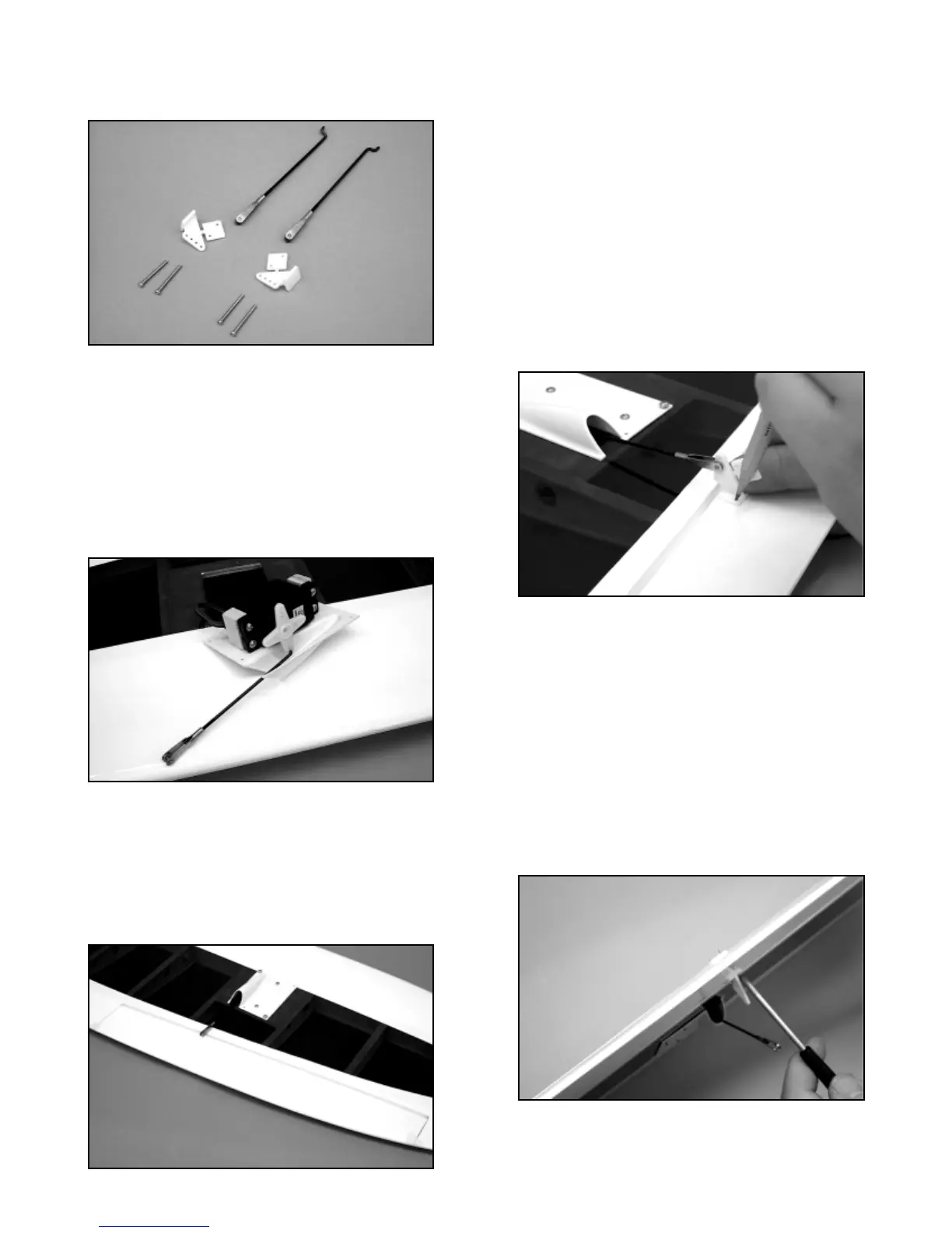
At one of the marks just made, drill a 3/32” dia. hole all the way
through the aileron, perpendicular to the bottom surface. Slip a
M2 x 3/4” bolt through the appropriate hole in the nylon control
horn and push the bolt through the aileron. Position the horn and
drill the remaining bolt hole, again perpendicular to the bottom
surface of the aileron. Thread another M2 x 3/4” bolt through the
nylon horn base and the aileron. Adjust the drilled holes as
needed to line-up with the holes in the nylon mounting base. Align
the holes in the base with the tips of the bolts protruding from the
top of the aileron. With a small Phillips screwdriver, thread the
bolts into the holes in the mounting base, securing the horn to the
aileron - do not over-tighten the bolts. Repeat this procedure with
the remaining wing panel. Use diagonal cutters to remove the
exposed tips of the bolts on top of the nylon base and file them
smooth. Connect the control links to the control horns.
FUEL TANK ASSEMBLY:
The 260cc (8.8oz.) fuel tank supplied with this kit is now
5