throttle in the low position. Allow muffler manifold pressure from
the tank vent line to get fuel to the carburetor. Avoid “choking” fuel
through the line by placing your finger over the carburetor. With
properly broken-in engines, these procedures should work
perfectly every time.
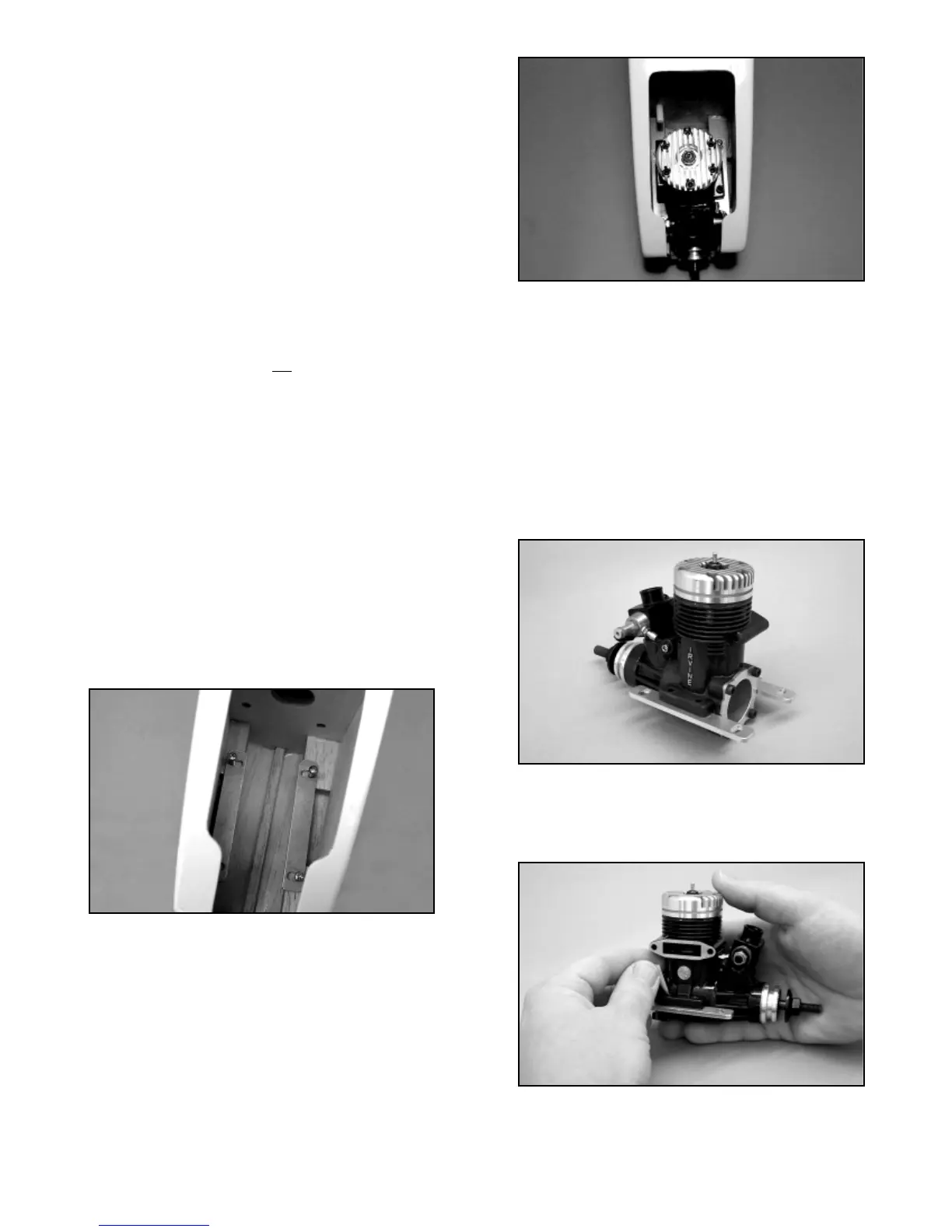
2-STROKE ENGINES:
If you plan to use a 2-stroke engine, some basic openings in the
nose of the fuselage must be made to allow for muffler clearance
and mounting, as well as an exit hole for the needle valve. In
addition, if you plan to use a fuel filler valve, such as the Du-Bro
#334 Kwik-Fill Fueling Valve or some other type of fueling system,
this will be the time to install it. For reference, the engine shown in
the following assembly and installation steps is the Irvine .46,
typical of engines in the .40 class.
The fuselage has the throttle pushrod housing tube already
installed. However, this tube has not
been glued in place and is
removable. The firewall has been pre-drilled for installing the
throttle tube on either side of the firewall. This allows for the
different locations of various engine throttle arms, including
4-strokes. Before starting the engine installation, be sure the
throttle pushrod tubing is on the correct side of the firewall for your
particular engine. The remaining hole in the firewall can be filled
with a short piece of rounded balsa, sanded smooth and fuel-
proofed with thin CA, dope or epoxy resin.
❑ 1) With the fuselage upside down on your workbench,
temporarily install the two aluminum motor mount rails onto the left
and right hardwood motor mount bearers in the nose of the
fuselage. Align the oblong holes over the pre-drilled bolt holes and
insert the four M3 x 20mm bolts with the large washers only (the
lock washers will only be used when the engine is final-mounted)
through the aluminum mount holes. Use a screwdriver to thread
the bolts in place but do not tighten them. The aluminum rails
should be just free enough to move.
❑ 2) With the muffler and needle valve removed, fit your engine
in place between the aluminum rails, with its mounting lugs on top
of the rails. Slide the engine into its approximate mounting position
with the prop hub just ahead of the front of the fuselage by
approximately 1/16” - 3/32”. This spacing will be the clearance for
the spinner backplate (temporarily mounting the spinner backplate
to the engine and using 1/16” scrap balsa “spacers” makes this
spacing easy and accurate). Be sure the aluminum motor mount
rails are against the sides of the engine case and the engine is
centered at the front. With the engine and aluminum mounts now
in position, lightly tighten the four motor mount bolts to hold the
aluminum rails in place. Remove the engine.
❑ 3) Use alcohol or acetone to clean the bottom surfaces of the
engine mounting lugs, removing any oil or grease. Do the same
thing to the tops of the aluminum motor mounts, cleaning them
completely. Apply 3 or 4 drops of thin CA glue to the bottom of
each mounting lug on the engine. Carefully place the engine
back into the nose of the airplane, positioning it with the proper
1/16” - 3/32” clearance for the spinner backplate. Hold the engine
in place to the aluminum rails and use a little accelerator to set the
CA glue.
❑ 4) Loosen and remove the four bolts holding the aluminum
rails in place and carefully remove the engine, with the attached
aluminum rails, from the nose of the model.
❑ 5) Use a shortened pencil with a sharp point to mark the
locations of the engines mounting holes onto the aluminum motor
mounts. To remember which rail fits on the right and left side of the
engine, mark them with an “R” and “L” (left and right).
Tap the aluminum mounts to free them from the engine. Use the
pencil marks to drill clearance holes through both motor mounts
for the engine mounting bolts (not supplied). If you use typical
6-32 socket head bolts for mounting the engine, the holes should
7