mount it and make the required hole in the side of the fuselage for
the fueling probe. Locate the aluminum bracket to the firewall,
(with the fuel valve in place), and mark the approximate location of
the required opening in the fuselage side. Like the needle valve
opening, start with a small drilled hole and open it up to match the
center of the fueling valve.
❑ 9) The engine compartment was fuel-proofed at the factory.
However, the exposed wood edges of the muffler and needle valve
openings should now be coated to make them fuel proof as well.
We suggest using clear dope or epoxy resin to seal the exposed
wood. To make the job look totally complete and custom, try using
flat white or flat black dope or other fuel-proof paint.
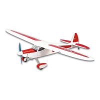
❑ 10) The fuel tank can now be installed. Apply a bead of silicon
sealer around the neck of the tank and install it into the fuel tank
compartment, through the top of the fuselage. Press the neck into
the hole in the firewall. Included in the kit contents is a balsa piece
measuring 5/16” x 3/4” x 3-3/16”. This is used to hold the fuel tank
in place at the rear. Position the balsa retainer directly behind the
tank, between the fuselage sides. Apply a couple of drops of thin
CA glue to each side of the balsa piece to hold it in place. If for
any reason you need to remove the tank, the balsa piece can be
easily popped loose and tank removed.
❑ 11) Apply a little thread-locking compound to the threads of the
M3 x 20mm mounting bolts. Install the lock washers onto each
bolt, followed by the larger flat washers. Install the engine and
aluminum rails into the engine compartment. Slip the four bolts
(with washers) into the oblong holes in the aluminum rails. Thread
the bolts into their blind mounting nuts and tighten the bolts firmly
to the wood motor mounts - be sure to maintain the 1/16” - 3/32”
spinner backplate clearance. Use medium fuel tubing (not
supplied) to now make the required connections between the
engine and fuel tank and the vent line and muffler manifold
pressure nipple.
The throttle linkage will be made during the radio installation
phase of these instructions. This completes the engine and fuel
tank installation.
4-STROKE ENGINES:
Installing the typical .40 - .52 4-stroke engine is similar to installing
2-stroke engines. However, there are obvious physical differences
in the basic configurations of these engines, including totally
different carburetor, throttle arm, and muffler locations. For
reference, the engine shown in the following steps is a Magnum
®
XLFS .52AR 4-stroke, (to more easily install this particular engine,
we reversed the carburetor position 180
O
on the intake manifold).
The engine compartment in the Rascal Forty will accept virtually
any make of 4-stroke engines in .40 to .52 c.i. sizes.
As mentioned in the 2-stroke instructions, the fuselage comes with
the throttle pushrod housing tube installed, but not yet glued in
place. The firewall has already been pre-drilled to allow installing
this tube on either side. Before starting the engine installation, be
sure the throttle pushrod tubing is on the correct side of the firewall
for your particular engine. The unused hole can be filled with a
short piece of dowel and sanded smooth. It should then be fuel-
proofed with thin CA, dope or epoxy resin.
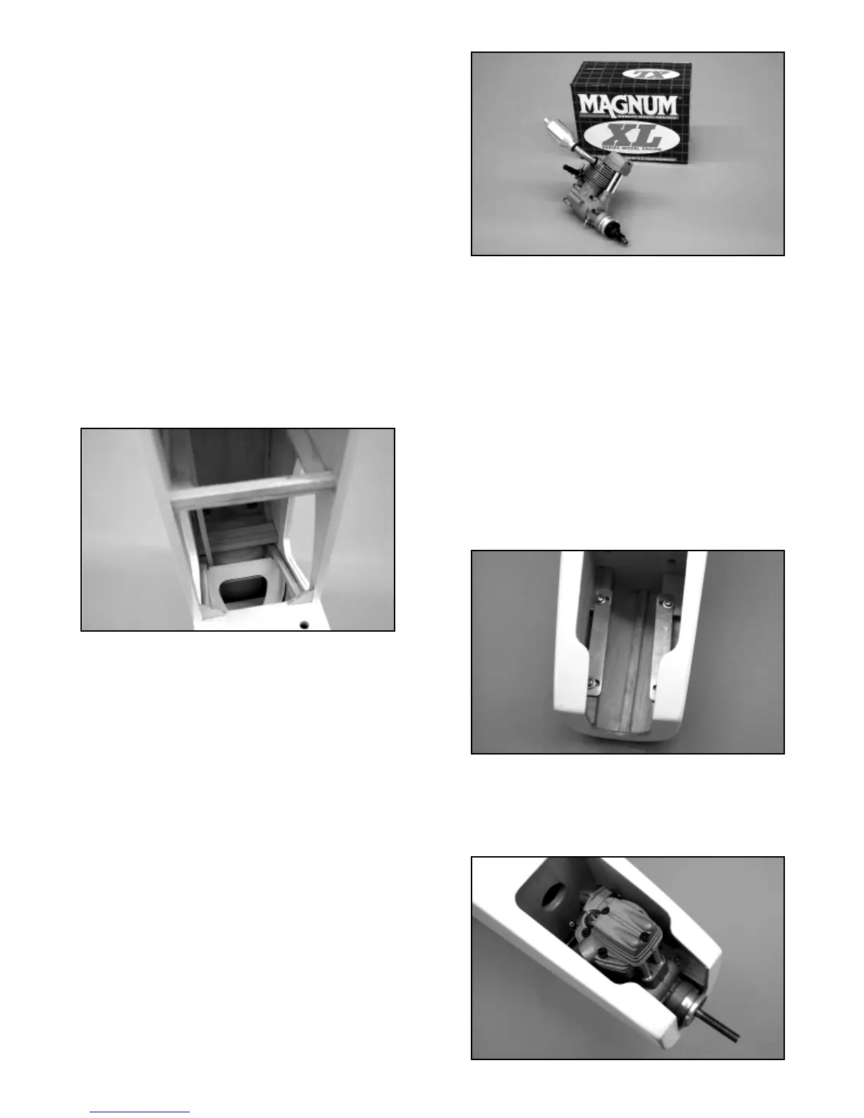
❑ 1) Place the fuselage upside down on your workbench and
temporarily install the two aluminum motor mount rails onto the
hardwood motor mount bearers built-in to the nose of the fuselage.
Align the oblong holes in the aluminum rails over the pre-drilled
holes in the wood bearers and insert the four M3 x 20mm bolts
with the larger washers only (the lock washers will only be used
when the engine is final-mounted) through the aluminum mount
holes. Use a screwdriver to thread the bolts in place but do not
tighten them. Leave the aluminum rails just free enough to move.
❑ 2) Remove the muffler header pipe and needle valve from the
engine. Fit the engine in place onto the aluminum rails. Slide the
engine to its approximate mounting position with the prop hub just
ahead of the front of the fuselage by approximately 1/16” - 3/32”.
This spacing will be the clearance for the spinner backplate
9