Do you have a question about the SIGLENT SDS2000X Plus Series and is the answer not in the manual?
Explains safety terms and symbols used in the manual and on the instrument.
Details the required operating conditions for temperature, humidity, and altitude.
Describes the necessity of adequate airflow for internal cooling fans.
Details the instrument's AC power voltage and frequency specifications.
Explains how to connect the power cord for line voltage and safety ground.
Recommends annual calibration by qualified personnel.
Provides instructions for cleaning the instrument exterior with a soft cloth.
Outlines conditions under which the instrument should not be operated.
Verifies that all items listed on the packing list have been delivered.
Details the oscilloscope's 3-year warranty and conditions.
Offers services like extended warranties and on-site maintenance.
Describes two methods for powering on the oscilloscope: Line and Manual.
Explains how to turn off the oscilloscope and fully power it down.
Explains how to check system status, including software and hardware versions.
Explains the need for a license to unlock software options.
Details safety precautions when using probes to avoid electric shock.
Explains the procedure for compensating probes to ensure accurate measurements.
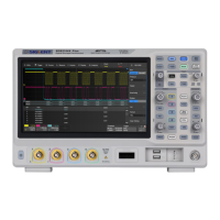
Provides an overview and identification of the oscilloscope's front panel components.
Identifies and describes the various connectors and features on the rear panel.
Details how to connect power supplies, LAN, USB peripherals, and probes.
Introduces the capacitive touch screen and its interaction methods.
Explains how to access functions and dialogs through the menu bar.
Describes the grid area, waveform display, and indicators on the grid.
Explains the elements within the channel descriptor box and bandwidth limit indicators.
Details the information displayed in the timebase and trigger descriptor boxes.
Explains the structure and use of dialog boxes for setting parameters.
Demonstrates how to use touch gestures for waveform adjustment and control.
Explains how to use a mouse and keyboard for instrument control.
Guides on changing the instrument's display language.
Provides an overview of the front panel design and its multi-function knobs.
Explains how to control vertical settings for channels, math, and reference.
Details how to adjust horizontal scale, zoom, roll mode, and trigger delay.
Explains the controls for trigger setup, mode, and level adjustment.
Describes how to switch between Run and Stop states for data acquisition.
Explains how the Auto Setup button optimizes waveform display settings.
Details the functions of Search, Navigate, History, and Decode buttons.
Explains how to use the cursors for measurements and selections.
Describes the function of the universal knob for adjusting and selecting parameters.
Explains the function of other buttons like Measure, Print, Touch, Default, etc.
Explains how to access functions using the drop-down menu bar.
Describes using descriptor boxes to access setup dialogs.
Explains using front panel shortcut buttons to recall functions.
Explains how to enable or disable analog and digital channels.
Details setting vertical scale, offset, coupling, and probe attenuation.
Introduces the SPL2016 logic probe for monitoring digital signals.
Explains how to turn digital channels on or off, similar to analog channels.
Details setting the position, height, and logic threshold for digital channels.
Explains how to adjust horizontal scale and trigger delay.
Covers interpolation modes, acquisition modes, and memory depth.
Describes entering and controlling Roll mode for continuous waveform display.
Explains Sequence mode for capturing multiple events with minimized dead time.
Details how to use History mode to view and analyze previously acquired frames.
Explains how to use the horizontal zoom function to magnify waveform details.
Explains the importance of triggering for stable waveform display and acquisition memory structure.
Guides on adjusting trigger level, mode, and source.
Explains how to set the trigger level for accurate waveform capture.
Describes Auto, Normal, and Stop modes for waveform acquisition.
Lists and describes various trigger types like Edge, Slope, Pulse, Video, etc.
Details how to set up an edge trigger, including source and slope.
Explains setting up a slope trigger with upper and lower levels.
Describes triggering based on pulse width specifications.
Explains video trigger settings for NTSC, PAL, and HDTV signals.
Details setting up window triggers, including Absolute and Relative types.
Explains triggering based on the time difference between edges.
Describes triggering when a signal disappears for a specified duration.
Explains triggering on pulses that cross one threshold but not another.
Describes triggering based on logic patterns of input signals.
Lists the available trigger sources (channels, EXT, AC Line) for different trigger types.
Explains Holdoff by Time and Holdoff by Event for stabilizing complex triggers.
Describes trigger coupling modes (DC, AC, HFR, LFR) for signal conditioning.
Explains how Noise Reject adds hysteresis to improve trigger immunity.
Details setting up Zone triggers to isolate specific events within defined areas.
Introduces supported serial bus protocols for triggering and decoding.
Details I2C signal settings, trigger conditions, and decode results.
Explains SPI signal settings, trigger conditions, and decode configuration.
Covers UART signal settings, trigger conditions, and serial decode.
Details CAN signal settings, trigger conditions, and serial decode.
Explains LIN signal settings, trigger conditions, and serial decode.
Details FlexRay signal settings, trigger conditions, and serial decode.
Covers CAN FD signal settings, trigger conditions, and serial decode.
Details I2S signal settings, trigger conditions, and serial decode.
Explains MIL-STD-1553B signal settings, trigger, and serial decode.
Introduces cursors as tools for rapid horizontal and vertical measurements.
Explains how to select and move cursors using gestures and the universal knob.
Introduces automatic measurements, statistics, and the Gate function.
Guides on selecting sources and parameters for measurements.
Lists and describes various vertical measurement parameters like Max, Min, Pk-Pk, etc.
Allows observing the change of selected measurement values over time.
Explains M1 and M2 display modes for showing multiple measurements.
Enables observing the distribution of measured values for parameters.
Activates a histogram to view the probability distribution of measured parameters.
Displays all selected measurement parameters for a channel simultaneously.
Helps measure parameters within a specified time range, ignoring outside data.
Introduces math traces, operators like addition, FFT, and formula editor.
Explains arithmetic operations like addition, subtraction, multiplication, and division.
Details differential (d/dt), integral (∫dt), and square root (√) operations.
Explains FFT analysis for frequency spectrum, including sample rate and points.
Guides on using the formula editor to create custom math functions.
Explains saving and recalling waveforms to memory for comparison.
Explains searching for specified events within a frame using indicators.
Introduces three navigate types: Search Event, Time, and History Frame.
Explains creating masks and defining rules for Pass/Fail evaluation.
Details methods for creating and loading masks using horizontal and vertical values.
Explains rules like "All In", "All Out", "Any In", and "Any Out" for Pass/Fail tests.
Introduces the counter for measuring frequency, period, and counting events.
Explains the three counter modes: Frequency, Period, and Totalizer.
Introduces power analysis functions and required accessories/licenses.
Details power quality parameters like active power, power factor, and voltage crest factor.
Explains analyzing current harmonics using FFT.
Describes inrush current, the large current surge during power supply switching.
Explains calculating power dissipated during switching periods and deskew calibration.
Measures the change rate of voltage or current during switching.
Analyzes control pulse signals of switching devices (MOSFETs).
Measures DC power supply ripple, representing output DC voltage quality.
Determines time taken for power supply output to reach steady state or fall.
Measures power supply response speed to output load changes.
Determines how the regulator suppresses ripple noise at different frequencies.
Tests overall power supply efficiency by measuring input and output power.
Describes the Bode plot function for frequency response analysis using AWG.
Covers DUT connection, AWG connection, and sweep parameter settings.
Details DUT input/output channels, channel gain, and AWG connection settings.
Explains setting sweep type (Simple, Vari-Level), frequency, and amplitude.
Covers amplitude, phase, cursors, and trace visibility settings.
Explains analyzing Bode plot curves using data lists and cursors.
Explains waveform display types: Vectors (line) and Dots (raw samples).
Uses color temperature to map waveform probability.
Controls how previous acquisitions are displayed with reduced intensity.
Explains grid display modes: M1 (8*10), M2 (2*2), M3 (no grid).
Introduces the built-in AWG functions and capabilities.
Explains how to turn the AWG output on and off.
Lists standard and arbitrary waveform types supported by the AWG.
Covers output load, overvoltage protection (OVP), and zero adjust.
Describes supported save types: Setup, Reference, Image, Waveform Data.
Explains saving and recalling oscilloscope setups to internal memory.
Details saving and recalling data to/from external USB storage devices.
Explains how to check system status, including software and hardware versions.
Guides on enabling or disabling the audible buzzer.
Provides instructions for upgrading the oscilloscope firmware via USB.
Explains how to select the display language from multiple options.
Guides on setting or disabling the screen saver function.
Covers LAN and VNC port settings for network connectivity.
Explains how to set the instrument's internal clock for accurate time logging.
Guides on installing software options using an activation key or USB disk.
Sets scaling strategy for horizontal and vertical axes when scale changes.
Guides on performing screen, keyboard, and LED tests for diagnostics.
Explains the self-calibration procedure to ensure precise measurements.
Resets the oscilloscope to factory or last saved settings.
Configures the "Power on Line" feature for automatic startup.
Explains controlling the oscilloscope via a web browser using its IP address.
Mentions SCPI commands via NI-VISA, Telnet, or Socket for remote control.
Provides steps to diagnose and resolve issues with no display after power on.
Offers solutions for when no waveform is displayed despite signal sampling.
Provides steps to stabilize a waveform that moves across the display.
Guides on resolving no display issues after using Run/Stop.
Offers solutions when the touch screen fails to respond to input.
Provides steps to troubleshoot issues with USB storage device recognition.
Provides contact details for SIGLENT's headquarters.
Provides contact details for SIGLENT Technologies NA, Inc.
Provides contact details for SIGLENT TECHNOLOGIES EUROPE GmbH.
| Channels | 2 or 4 |
|---|---|
| Vertical Sensitivity | 1 mV/div to 10 V/div |
| Input Coupling | DC, AC, GND |
| Maximum Input Voltage | 400 V (DC + AC peak) |
| Operating Temperature | 0 °C to +50 °C |
| Bandwidth | 100 MHz, 300 MHz |
| Waveform Capture Rate | 500, 000 wfm/s |
| Vertical Resolution | 8 bits |
| Display | 10.1-inch capacitive touch screen |
| Input Impedance | 1 MΩ ± 1% |
| Trigger Types | Edge, Pulse, Video, Window |
| Interfaces | USB Host, USB Device, LAN |
| FFT | Yes |