Do you have a question about the SIGLENT SDS1202X-E and is the answer not in the manual?
Use only the power cord designed for the instrument and authorized by local country.
Ensure the instrument is grounded correctly before connecting input/output terminals to avoid shock.
Do not connect the signal wire to a high voltage as its potential equals earth.
Check all ratings and instructions before connecting to avoid fire or electric shock.
Ensure no overvoltage reaches the product to prevent operator danger from electrical shock.
Operate in ESD-protective areas and ground conductors to avoid static discharge damage.
Ensure good ventilation to prevent temperature increase that could damage the instrument.
Do not touch exposed contacts or components when the power is on.
Use only the specified fuse for the instrument to ensure safety and proper function.
Explains warning and caution statements used within the manual text.
Defines danger, warning, and caution terms that may appear directly on the product.
Lists and explains symbols that may appear on the product for hazard identification.
Defines the scope of measurements the oscilloscope can perform within specified categories.
Details definitions for Measurement Categories II, III, and IV for electrical installations.
Specifies the instrument is intended for indoor use in a clean, dry environment.
Lists operating and non-operating temperature ranges for the instrument.
Specifies operating and non-operating humidity limits for the instrument.
Lists operating and non-operating altitude limits for the instrument.
States the product is powered by mains conforming to installation category II.
Specifies the acceptable degree of pollution for the oscilloscope's operating environment.
Provides general care instructions, such as avoiding direct sunlight for extended periods.
Outlines steps for cleaning the instrument and probe using appropriate materials.
Lists safety standards recognized by U.S. testing laboratories that the product complies with.
Lists safety standards recognized by Canadian certification bodies that the product complies with.
Introduces preparations for first-time oscilloscope use, covering panels and interface.
Details initial checks of shipping container, instrument, and accessories for damage.
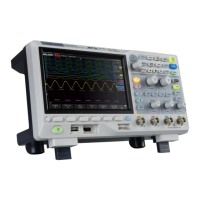
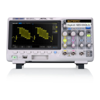
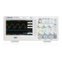
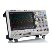
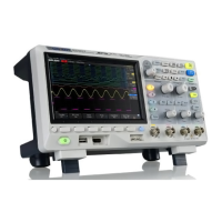
Presents visual representations and measurements of the oscilloscope's physical appearance.
Covers essential steps before operating the oscilloscope, like connecting power and probes.
Provides a detailed layout of the oscilloscope's front panel controls and displays.
Details the oscilloscope's rear panel connections and ports.
Explains the functions of various controls on the front panel, grouped by system.
Describes the elements and status indicators displayed on the oscilloscope's screen.
Explains how to use a security lock to fix the oscilloscope's location.
Inspect shipping container, instrument, and accessories for damage or completeness.
Details the physical dimensions and front/top views of the 2-channel scope.
Covers essential steps before operating the oscilloscope, like connecting power and probes.
Provides an overview of the SDS1000X-E 2-channel scope front panel with numbered components.
Details the rear panel of the SDS1000X-E 2-channel scope with numbered ports and features.
Explains the functions of various controls on the front panel, grouped by system.
Describes the elements and status indicators displayed on the oscilloscope's screen.
Explains how to use a security lock to secure the oscilloscope to a fixed location.
Quickly enter roll mode for slow waveform scrolling, 50ms/div to 100S/div.
Enable or disable search function to find specified events in acquired data.
Adjust horizontal position; pressing resets trigger delay to zero.
Adjust horizontal time base; pressing activates Zoom function.
Adjust vertical position; pressing resets position to zero.
Adjust vertical scale; pressing switches between Coarse and Fine modes.
Enter MATH function menu for operations like addition, subtraction, FFT.
Enter REF function menu to display and compare reference waveforms.
Open digital channel function menu (Optional); SDS1000X-E (4-channel) supports 16 channels.
Enter the TRIGGER function menu for abundant advanced trigger functions.
Set the trigger mode to Auto, displaying signal activity even without triggers.
Set the trigger mode to Normal, triggering only on specified conditions.
Set the trigger mode to Single, waiting for condition then stopping acquisition.
Adjust trigger level; pressing resets level to waveform center.
Enable automatic waveform setting for optimal display of vertical scale, time base, trigger.
Set acquisition state to Run (yellow light) or Stop (red light).
Enter CURSOR function menu for manual and track cursor modes.
Enter DISPLAY menu, enable persist, set grid, intensity, and transparency.
Enter UTILITY menu for system status, self-calibration, sound, and language settings.
Shortcut to clear measurement counts or persistence display.
Enter MEASURE menu for measurement parameters, statistics, and gate settings.
Enter ACQUIRE menu for acquisition mode, memory depth, and interpolation settings.
Enter SAVE/RECALL menu to save setups, waveforms, pictures, CSV files.
Reset the oscilloscope to user default setup configuration.
Enter history mode to record and replay up to 80000 waveforms.
Enter DECODE menu for serial bus decoding (I2C, SPI, UART, CAN, LIN).
Turn on/off navigate function for Time, Search Event, History Frame.
Displays the SIGLENT logo, identifying the manufacturer.
Shows channel labels and waveform colors matching input connectors.
Indicates trigger status: Ready, Auto, Stop, Arm, Trig’d, FStop.
Represents time per grid; adjusted via HORIZONTAL SCALE Knob.
Adjust trigger position; pressing knob resets to zero.
Indicates the trigger delay on the waveform display.
Displays the frequency value of the trigger channel.
Shows current sampling rate and memory depth.
Displays current trigger type, source, condition, coupling, and level.
Shows probe attenuation, input impedance, coupling, and vertical scale.
Displays trigger level position and value, matching trigger channel color.
Indicates connection status for USB Host, LAN, and WLAN ports.
Displays the function menu of the selected button after pressing the corresponding soft key.
Details how to enable and configure analog input channels, using CH1 as an example.
Explains how to adjust the vertical scale in Coarse or Fine mode using the Vertical Variable Knob.
Adjust vertical position; pressing knob resets position to zero.
Set coupling mode (DC, AC, GND) to filter unwanted signals.
Set bandwidth limit (Full or 20M) to reduce display noise.
Set probe attenuation factor (e.g., 1X, 10X) for correct vertical readouts.
Select amplitude display unit (V or A) for the current channel.
Adjust deskew for analog channels within ±100ns range.
Turn On/Off to invert the displayed waveform values.
Set whether the current channel waveform is visible on the display.
Adjust horizontal time base using the HORIZONTAL Scale Knob; affects sample rate or zoom.
Adjust trigger delay using the Position Knob to move trigger point horizontally.
Enter Roll mode for slow waveform scrolling, similar to a strip chart recorder.
Horizontally expand part of the normal window for detailed analysis using split screen.
Start, stop, or single-step waveform acquisition using Run/Stop and Single buttons.
Introduces sampling and acquisition modes, theory, sample rate, and bandwidth.
Explains the Nyquist sampling theorem and its relation to signal reconstruction without aliasing.
Explains how the sample rate is determined by the horizontal scale and its effects on waveform display.
Details memory depth, its impact on waveform acquisition, and storage capacities.
Explains the real-time sampling mode and its functionality.
Describes interpolation methods (X and Sinx/x) for improving waveform visibility.
Explains acquisition modes (Normal, Peak Detect, Average, Eres) for generating waveform points.
Select display format: YT (Volt vs. Time) or XY (Volt vs. Volt).
Explains Sequence mode for improved capture rate and capturing low-probability events.
Explains trigger source options including Analog channels, EXT, EXT/5, and AC Line.
Details trigger modes: Auto, Normal, and Single, and their appropriate use cases.
Explains how to adjust the trigger level using the Trigger Level Knob for stable triggering.
Describes trigger coupling modes (DC, AC, LF Reject, HF Reject) to filter noise and improve trigger stability.
Explains Trigger Holdoff for stably triggering complex waveforms by setting a wait time.
Details Noise Rejection for reducing trigger sensitivity to noise by increasing hysteresis.
Lists trigger types: Edge, Slope, Pulse, Video, Window, Interval, Dropout, Runt, Pattern.
Explains Edge trigger for distinguishing trigger points based on specified edge and level.
Details Slope trigger for detecting transitions between levels over a specific time.
Explains Pulse trigger for capturing pulses with a specified width and polarity.
Describes Video trigger for capturing standard analog video signals based on vertical/horizontal intervals.
Details Window trigger using high and low levels to trigger on signal passing through defined levels.
Explains Interval trigger for detecting time differences between neighboring edges meeting time limits.
Details Dropout trigger for detecting missing edges or states based on timeout settings.
Explains Runt trigger for detecting pulses crossing one threshold but not another.
Describes Pattern trigger for identifying conditions by looking for specified logical patterns across channels.
Introduces I2C trigger and decode setup for serial communication analysis.
Introduces SPI trigger and decode setup for serial communication analysis.
Introduces UART trigger and decode setup for serial communication analysis.
Introduces CAN trigger and decode setup for serial communication analysis.
Introduces LIN trigger and decode setup for serial communication analysis.
Guides saving analog or math waveforms to internal memory for later recall.
Explains how to display saved reference waveforms on the screen for comparison.
Details adjusting the vertical scale and position of reference waveforms.
Explains how to clear reference waveforms, typically by overwriting with new data.
Lists units for various math operations like addition, subtraction, multiplication, division, and FFT.
Covers math operations: Addition/Subtraction, Multiplication/Division, FFT, Differential, Integral, Square Root.
Explains d/dt operation for calculating discrete time derivative of a selected source.
Details dt operation for calculating integrals, used for pulse energy or area measurement.
Explains square root calculation for a selected source, showing holes for undefined values.
Explains X cursors as vertical lines for measuring time or frequency on FFT waveforms.
Describes Y cursors as horizontal lines for measuring voltage or current.
Lists 15 kinds of voltage parameter measurements and 11 kinds of time parameter measurements.
Lists 15 kinds of voltage parameter measurements including Peak-Peak, Maximum, Minimum, Amplitude, Top, Base.
Lists 11 kinds of time parameter measurements like Period, Frequency, Width, Rise Time, Fall Time.
Lists 10 kinds of delay measurements, measuring time differences between channels.
Explains performing automatic measurements by selecting voltage or time parameters via Measure function.
Details measuring all voltage, time, and delay parameters simultaneously and displaying results.
Explains gate measurement to perform selections within upper/lower limits, affecting parameter measurements.
Describes clearing all displayed measurement parameters using the Clear softkey.
Explains selecting display types: Vectors (lines) or Dots (points) for waveform visualization.
Details using color temperature to reflect waveform probability, with warmer colors for higher probability.
Explains Persistence settings (Off, Variable, Infinite) to control how previous acquisitions are displayed.
Describes clearing the entire display and acquiring new waveforms.
Explains selecting grid types: 14x8, 2x2, or no grid.
Details adjusting waveform intensity to view noise and detail, affecting analog channels only.
Explains adjusting grid brightness for better visibility, with a default of 40%.
Describes adjusting transparency of message boxes for better viewing convenience.
Lists supported save types: Setups, Reference, BMP, JPG, PNG, Binary, CSV, Matlab, Default Key, Bin2CSV Tool.
Guides saving and recalling oscilloscope settings (Setups) to internal memory.
Explains saving and recalling files (Setups) to/from external USB flash devices.
Covers disk management operations: creating, deleting, and renaming files/folders on USB storage.
Details connecting digital probes to the oscilloscope and device-under-test for measurements.
Explains acquiring digital waveforms by sampling and comparing input voltage to logic threshold.
Guides adjusting the vertical height of digital traces (Low, Middle, High display type).
Explains positioning digital traces vertically for better viewing convenience.
Details configuring and switching individual digital channels on or off.
Explains switching all digital channels or groups of channels on or off.
Guides setting logic thresholds (TTL, CMOS, LVCMOS) for digital signal interpretation.
Explains configuring and displaying digital channels as buses (hex or binary) for easier analysis.
Details adjusting deskew for digital channels to align timing between channels.
Covers various system settings including status, calibration, sound, language, IO, web server.
Describes safely removing USB devices after firmware updates or operations.
Displays oscilloscope system information: startup times, software/hardware versions, serial number.
Guides performing self-calibration to ensure accurate measurements and optimal working state.
Explains Quick-Cal for correcting temperature-induced measurement deviations.
Details enabling/disabling beeper sounds for key presses and prompts.
Explains selecting the menu language from available options.
Details setting up and performing pass/fail tests to verify waveform compliance to parameters.
Explains saving and recalling test masks to internal memory or external USB devices.
Describes the AWG features, including standard and arbitrary waveforms.
Covers IO interface settings for USB, LAN, and WLAN communication with PC.
Describes accessing and controlling the oscilloscope via a web browser using its IP address.
Provides steps to update firmware and configuration files using a USB flash driver.
Guides performing self-tests for screen, keyboard, and LED components.
Details setting the screen saver time or disabling it to prevent screen burn-in.
Explains setting reference position for vertical and horizontal scales to remain stationary during changes.
Describes enabling/disabling automatic power-on or requiring manual power button press.
Explains viewing installed options or activating new license codes.
Guides connecting AWG via USB/LAN and enabling/disabling its output.
Explains setting standard waveforms (Sine, Square, Ramp, Pulse, Noise, DC, Arb) and their parameters.
Details AWG settings: Output Load, Sync Output, OVP, Default, Zero Adjust.
Accesses AWG system information and update functions.
Describes safely removing AWG devices after update operations.
Provides steps to perform Bode Plot analysis using an external AWG to measure gain and phase.
Guides configuring parameters for the external AWG used in Bode Plot II.
Provides examples for Simple Sweep and Vari-level Sweep operations for Bode plot.
Provides an example of performing a simple sweep operation for Bode plot analysis.
Demonstrates Vari-level sweep for specifying frequency/amplitude relationships for Bode plot.
Explains setting search parameters like search type (Edge, Slope, Pulse, Interval, Runt).
Describes how search results are displayed, indicating event numbers.
Guides navigating through time using playback controls or selecting specific time values.
Explains navigating through recorded history frames using playback controls or frame number selection.
Guides navigating to found search events using previous/next event controls.
Provides solutions for issues with the screen displaying nothing after power on.
Offers solutions for problems where signals are sampled but no waveform appears on the screen.
Provides steps to resolve unstable waveform displays by checking trigger settings.
Offers troubleshooting for issues where the display remains blank after pressing Run/Stop.
Suggests solutions for ladder-like waveform displays, relating to time base and display type.
Provides steps to troubleshoot PC connection failures via USB, checking IO settings.
Offers solutions for the oscilloscope not recognizing USB storage devices, including checks and restarts.
| Bandwidth | 200 MHz |
|---|---|
| Sample Rate | 1 GSa/s |
| Channels | 2 |
| Memory Depth | 14 Mpts |
| Waveform Capture Rate | 100, 000 wfm/s |
| Vertical Resolution | 8 bits |
| Input Impedance | 1 MΩ ±2% || 16 pF ±3 pF |
| Input Coupling | DC, AC, GND |
| Operating Temperature | 0 °C to +50 °C |
| Display | 7-inch TFT-LCD (800x480) |
| Vertical Sensitivity | 500 µV/div to 10 V/div |
| Interfaces | USB Host, USB Device, LAN |
| Math Functions | +, -, *, /, FFT |
| Trigger Types | Edge, Pulse, Video, Slope |