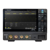
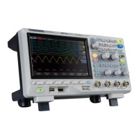
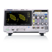
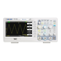
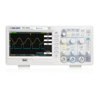
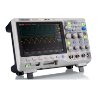
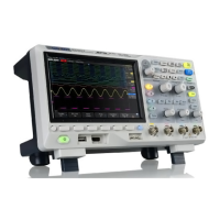
Do you have a question about the SIGLENT SDS1204X-E and is the answer not in the manual?
Essential safety guidelines for instrument operation and user protection.
Guidelines for safe handling, operation in hazardous conditions, and maintenance.
Defines WARNING and CAUTION statements used within the manual.
Defines DANGER, WARNING, and CAUTION terms found on the product.
Illustrates common safety symbols found on the product.
Oscilloscope usage within specified measurement categories.
Defines categories II, III, and IV for electrical measurements.
Specifies operating environment, temperature, humidity, altitude, and pollution degree.
Defines installation (overvoltage) categories I and II for safe operation.
Selecting trigger source and setting trigger modes (Auto, Normal, Single).
Setting trigger level and coupling modes for stable triggering.
Configuring holdoff time, noise rejection, and trigger event types.
Steps to set up I2C signal parameters for triggering and decoding.
Steps to set up SPI signal parameters for triggering and decoding.
Steps to set up UART signal parameters for triggering and decoding.
Steps to set up CAN signal parameters for triggering and decoding.
Steps to set up LIN signal parameters for triggering and decoding.
Covers voltage, time, and delay measurement types.
Performing automatic and displaying all parameter measurements.
Using gate measurement and clearing measurement results.
Setting display type (Vectors/Dots) and color temperature.
Configuring persistence and clearing the display.
Solutions for dark screen, missing waveforms, or no display after Run/Stop.
Solutions for unstable or ladder-like waveform displays.
Troubleshooting USB connection and storage device recognition.
| Bandwidth | 200 MHz |
|---|---|
| Channels | 4 |
| Memory Depth | 14 Mpts |
| Vertical Resolution | 8 bits |
| Max Input Voltage | 400 V (DC+AC Peak) |
| Operating Temperature | 0 °C to +50 °C |
| Sample Rate | 1 GSa/s |
| Display | 7-inch TFT-LCD, 800x480 resolution |
| Vertical Sensitivity | 500 µV/div to 10 V/div |
| Timebase Range | 2 ns/div to 50 s/div |
| Connectivity | USB Host, USB Device, LAN |
| Trigger Types | Edge, Pulse, Slope, Video, Runt, Pattern |
| Interfaces | USB Host, USB Device, LAN |
| Math Functions | +, -, *, /, FFT |
| FFT Window Functions | Rectangular, Hanning, Hamming, Blackman |
| Weight | 2.6 kg |
