Do you have a question about the SIGLENT SDS1000X-E Series and is the answer not in the manual?
Provides an overview of the manual's content, including safety and basic operation.
Safety precaution for using the correct power cord.
Safety precaution for electrical grounding.
Safety precaution for signal wire connection.
Safety advice before connecting the instrument.
Safety measure against overvoltage hazards.
Safety for preventing damage from static discharge.
Safety for maintaining instrument temperature.
Safety warning about touching live parts.
Safety instruction regarding fuse usage.
Safety rule about operating with covers removed.
Safety advice on handling faulty instruments.
Safety warning for humid environments.
Safety rule for hazardous atmospheres.
Maintenance advice for product longevity.
Precautions during instrument transportation.
Defines WARNING and CAUTION statements in the text.
Defines DANGER, WARNING, and CAUTION labels on the device.
Identifies common safety symbols on the instrument.
Defines the scope of measurement categories.
Explains categories II, III, and IV with examples.
General conditions for operation.
Operating and non-operating temperature ranges.
Operating and non-operating humidity limits.
Operating and non-operating altitude limits.
Specifies the product's power input category.
Defines overvoltage categories I and II.
Specifies the acceptable pollution level for operation.
Explains the need for free air circulation.
Details voltage and frequency requirements.
Note on automatic voltage adjustment.
General maintenance advice.
Steps for cleaning the oscilloscope.
Lists relevant US safety standards.
Lists relevant Canadian safety standards.
Introduces initial preparations for using the oscilloscope.
Describes how to set the vertical system of the oscilloscope.
Describes how to set the horizontal system of the oscilloscope.
Introduces how to set the sampling system of the oscilloscope.
Procedures for inspecting the shipping container and instrument.
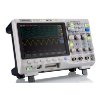
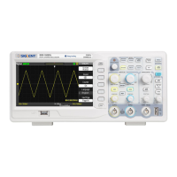
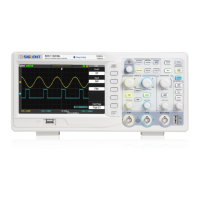
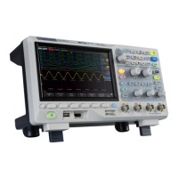
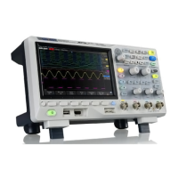
Visual representation of the oscilloscope's physical layout.
Steps to ready the oscilloscope for initial operation.
The main display screen of the oscilloscope.
Multi-functional knob for menu navigation and parameter adjustment.
Buttons for accessing primary oscilloscope functions.
Controls the acquisition state of the oscilloscope.
Automatically configures oscilloscope settings for optimal display.
Button to access and configure trigger settings.
Controls related to the horizontal time base and position.
Controls related to the vertical scale and position.
Provides an easy way to carry the instrument.
Hole for securing the instrument with a lock.
Interface for network connectivity and remote control.
BNC port for outputting trigger or pass/fail signals.
Interface for SCPI remote control commands.
Controls and functions related to the horizontal axis.
Controls and functions related to the vertical axis.
Selects the signal used for triggering.
Sets the oscilloscope's trigger behavior (Auto, Normal, Single).
Sets the voltage threshold for triggering.
Filters the signal path for trigger stability.
Sets the time the oscilloscope waits before re-arming the trigger.
Reduces the possibility of triggering on noise.
Selects the specific trigger condition (e.g., Edge, Pulse).
Manages the sampling and acquisition process.
Explains the principles of signal sampling and reconstruction.
Sets the number of waveform points stored per sample.
Determines how waveform points are generated from samples.
Triggers and decodes I2C serial communication signals.
Triggers and decodes SPI serial communication signals.
Triggers and decodes UART serial communication signals.
Triggers and decodes CAN serial communication signals.
Triggers and decodes LIN serial communication signals.
Stores current waveforms to internal memory for later recall.
Shows saved reference waveforms on the screen.
Modifies the scale and position of reference waveforms.
Removes saved reference waveforms from memory.
Specifies units for various math operations.
Details arithmetic and advanced math operations.
Vertical markers for time or frequency measurements.
Horizontal markers for voltage or current measurements.
Instructions for using cursors to perform measurements.
Defines voltage, time, and delay measurement parameters.
Performs automated measurements of selected parameters.
Measures all available voltage, time, and delay parameters.
Measures parameters within specified upper and lower limits.
Clears all displayed measurement parameters.
Sets waveform display style (Vectors or Dots).
Controls how previous acquisitions are displayed.
Clears all waveforms from the screen.
Selects the grid layout for the display.
Adjusts the brightness of waveform display.
Adjusts the brightness of the oscilloscope grid.
Adjusts the transparency of message boxes.
Specifies the format for saving setups, waveforms, and images.
Saves and loads oscilloscope settings to internal memory.
Saves and loads settings to/from a USB storage device.
Manages files and folders on the USB storage device.
Instructions for connecting digital probes to the oscilloscope.
Starts acquiring waveforms from the digital channels.
Sets the voltage threshold for digital signal interpretation.
Configures and displays digital channels as a bus.
Adjusts timing differences between digital channels.
Displays the oscilloscope's system information.
Performs self-calibration for optimal measurement accuracy.
Verifies waveform compliance against specified parameters.
Controls the external Arbitrary Waveform Generator (AWG).
Configures oscilloscope communication interfaces (USB, LAN, WLAN).
Updates the oscilloscope's software and configuration.
Runs diagnostic tests on screen, keyboard, and LEDs.
Steps to execute a Bode plot measurement.
Configures parameters for the external AWG.
Example of performing a simple frequency sweep.
Example of performing a variable amplitude frequency sweep.
Configures search parameters like type and thresholds.
Displays the number of found events during search.
Navigates through time-based events in the waveform.
Navigates through recorded waveform frames.
Navigates to specific search events in the waveform.
Records and replays waveforms before the Run/Stop button press.
Solutions for a blank display after power on.
Troubleshooting steps when no waveform appears.
Diagnosing and fixing unstable waveform display issues.
Resolving issues when the display stops after Run/Stop.
Fixing ladder-like waveform display by adjusting settings.
Resolving problems with USB PC connectivity.
Troubleshooting unrecognized USB storage devices.
| Channels | 2 or 4 |
|---|---|
| Memory Depth | 14 Mpts |
| Vertical Resolution | 8 bits |
| Vertical Sensitivity | 1 mV/div to 10 V/div |
| Input Coupling | DC, AC, GND |
| Operating Temperature | 0 °C to +50 °C |
| Bandwidth | 100 MHz, 200 MHz |
| Sample Rate | 1 GSa/s |
| Display | 7 inch TFT-LCD (800x480) |
| Interfaces | USB Host, USB Device, LAN |
| Math Functions | +, -, *, /, FFT |
| FFT Window Functions | Hanning, Hamming, Rectangular, Blackman-Harris |
| FFT Vertical Scale | dB |
| FFT Horizontal Scale | Frequency |
| Trigger Types | Edge, Pulse, Slope, Video |
| Dimensions | 303 mm |
| Weight | 2.5 kg |
| Waveform Capture Rate | 400, 000 wfm/s |
| Input Impedance | 1 MΩ ±1%, 15 pF ±3 pF |