M O D E S O F O P E R A T I O N
pressing the zero span button on the Sweep Settings control panel. The first time you enter zero span
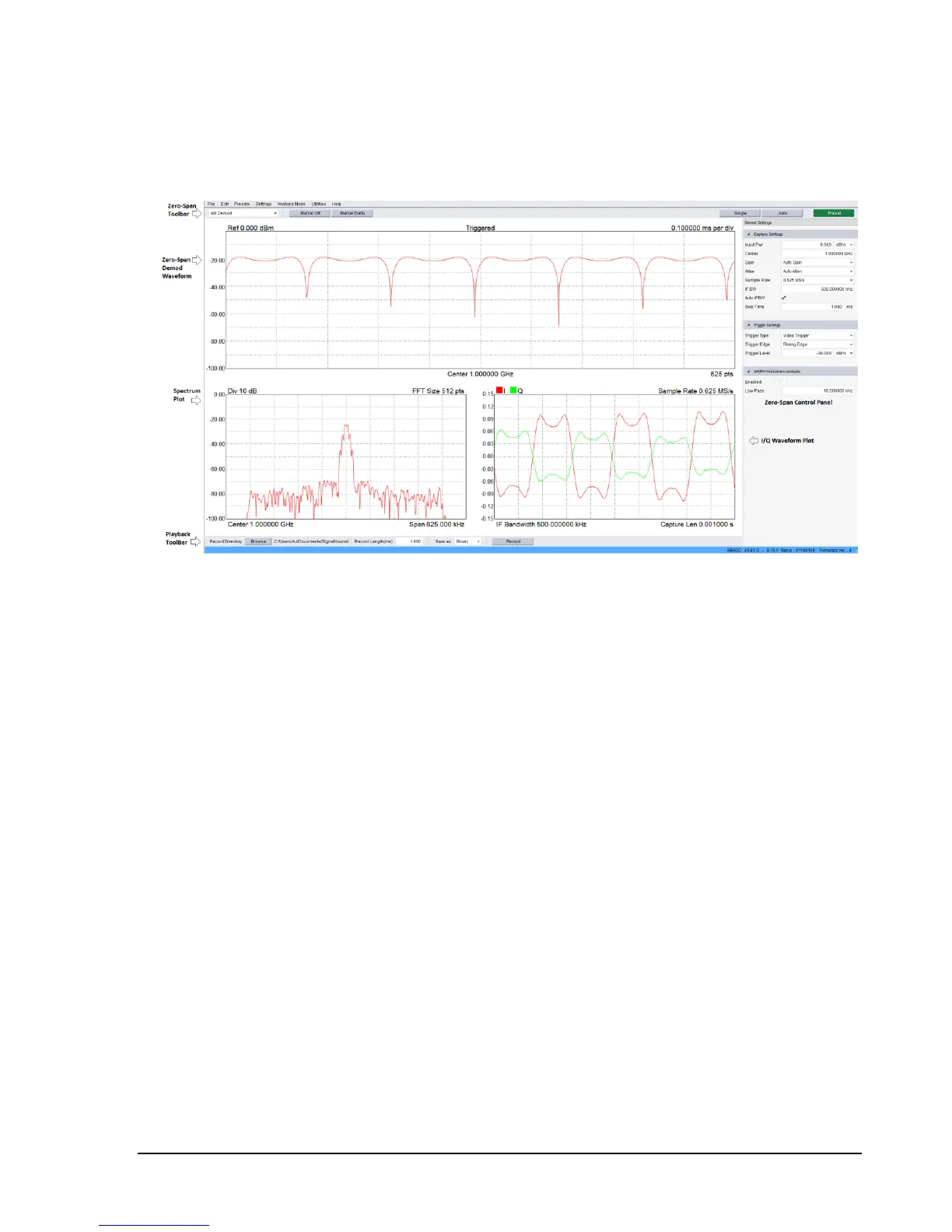
mode the application will appear as below.
The application window will be split into multiple viewports and contain a control panel for controlling
zero span sweeps. Zero span mode offers three viewports,
1) Demodulation Waveform Plot – Shows the results of performing AM/FM/PM demodulation.
The waveform is plotted as Amplitude/Frequency/Phase over time depending on the
modulation type selected.
2) Spectrum Plot – Shows the frequency spectrum of the zero span capture. The plot shows the
amplitude over frequency of the waveform signal.
3) I/Q Waveform Plot – Plots the individual I and Q channels as amplitude over time.
The control panel contains inputs for controlling the capture settings of the device as well as specifying
trigger conditions for the zero span sweeps. You can specify a video trigger, external trigger, or no
trigger. Video triggers allow you to begin the sweep only after a signal exceed the amplitude specified in
the Video Trigger input. This is useful when you need to analyze a periodic transmission.
If your transmitter has a trigger output, you can route this to the BB60 trigger in. Select “external
trigger” to cause the zero-span sweep to begin after this hardware trigger. You can trigger on the
rising edge or falling edge of a signal. A 3.3V CMOS trigger with a 50 ohm output impedance is
ideal, but 5V logic with a 50 ohm output impedance is acceptable. Higher or lower output
impedance may work with a short BNC cable, but longer cables may cause issues with reflection.
If your trigger output is sensitive to loading, start zero span mode with external trigger enabled
before connecting your trigger, to ensure the BB60 trigger port is configured as an input.
 Loading...