T A K I N G M E A S U R E M E N T S
Min and Max hold traces are another way to capture intermittent hard to view signals. Min and max hold
keep track of the minimum and maximum values over a period of time storing them in a separate
viewable trace.
Measuring Channel Power 5.5
The Control Panel allows you to control the channel power utility. Channel width is width in Hz of the
band whose power you wish to measure. Channel spacing refers to the center-to-center frequency
difference between the center channel and adjacent channels. Between channels, there is typically (but
not always) a small guard band whose power is ignored.
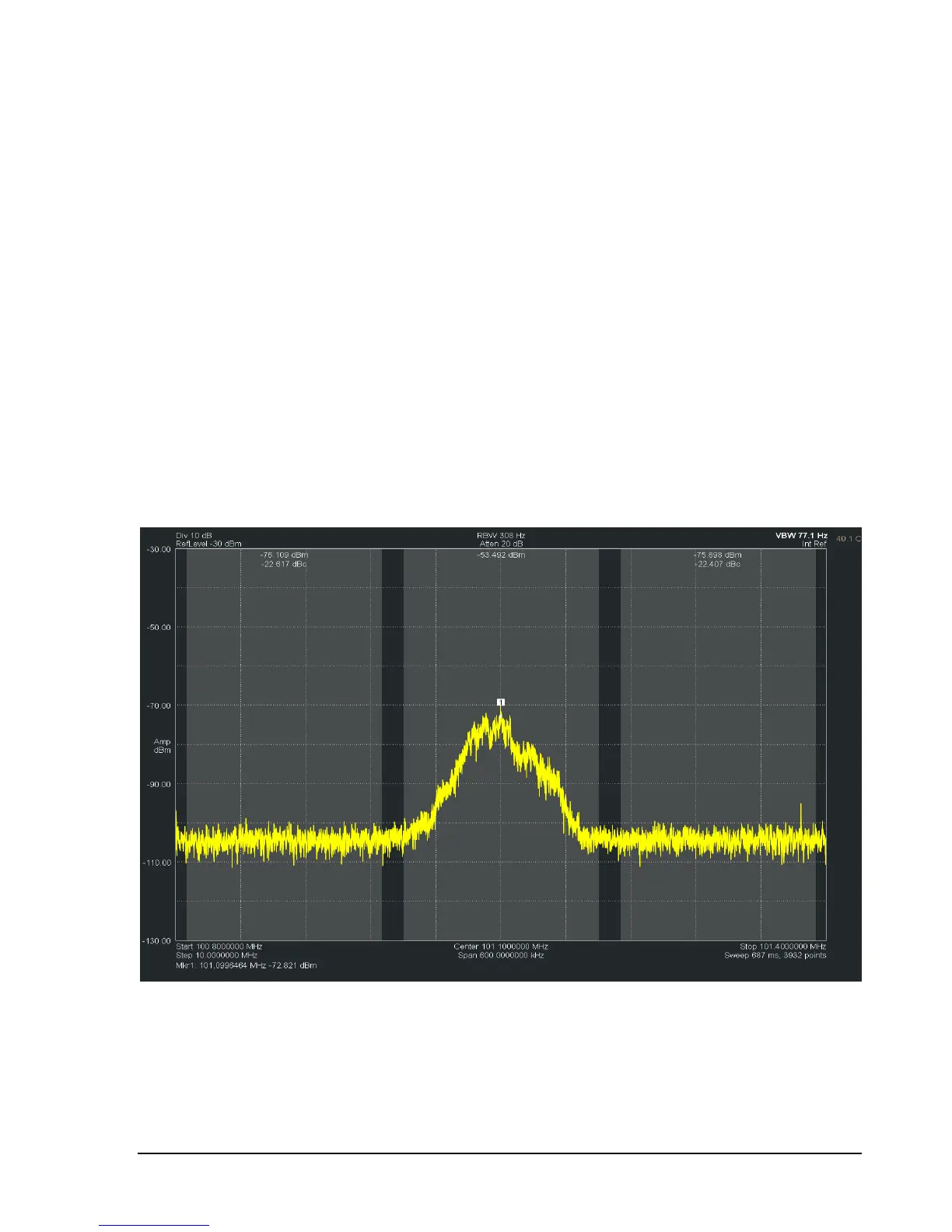
For example, the image below shows a channel bandwidth of 180 kHz and spacing of 200 kHz. The
image shows the FM station 101.1 in the center channel. Each channel will be integrated and the
resulting power is display at the top of the channel.
The adjacent channels also show the channel power as well as the difference in power between the
center channel and itself. In the example below the difference might be used to determine if any power is
“leaking” into an adjacent FM band.
For best results, set your video processing to AVERAGE, POWER, and turn spur reject off. A native
bandwidth should be selected for the most accurate power measurements. The software will set most of
this up for you automatically.
 Loading...