-9-
Light Wiring Connections:
Red: (8 AWG) +12VDC Power - The two large red wires exiting the back
of the siren should be connected to +12VDC through a fuse rated
for the TOTAL current draw of ALL of the lights controlled by this
unit. They will supply the power to the lights hooked up to the 9-
pin connector. You must connect BOTH red wires.
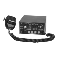
9-Pin Connector
(REFER TO THE LIGHT WIRE DIAGRAM ON
THE NEXT PAGE FOR PROPER WIRE SIZES!)
The electrical connections for slide
switch outputs, and for the push
button light functions outputs are
located on the square 9-pin
connector (part #SWH-49) on the
back of the siren.
Empty: (Pin 1)
Empty: (Pin 2)
Orange: (Pin 3) L1 Output – Output power to lights activated when the slide
switch is in the 1
st
, 2
nd
, or 3
rd
position.
Yellow: (Pin 4) S4 Output - Output power to lights controlled by S4 button.
Green: (Pin 5) S2 Output - Output power to lights controlled by S2 button.
Blue: (Pin 6) S3 Output - Output power to lights controlled by S3 button.
Violet: (Pin 7) S1 Output - Output power to lights controlled by S1 button.
Gray: (Pin 8) L2 Output – Output power to lights activated when the slide
switch is in the 2
nd
or 3
rd
position.
White: (Pin 9) L3 Output – Output power to lights activated when the slide
switch is in the 3
rd
position.
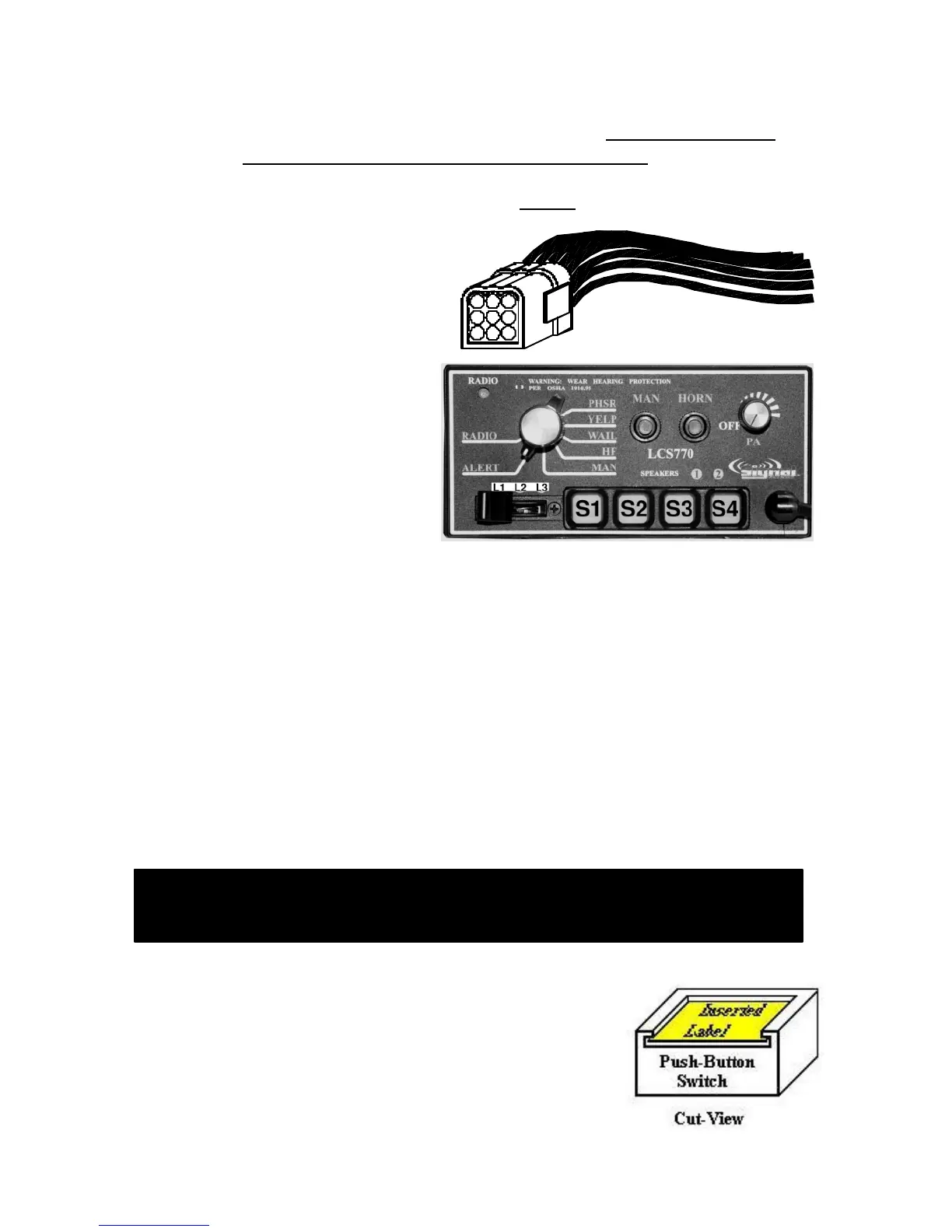
LABEL INSERTION: Once the wire connections
have been made to S1 through S4, labels can be
inserted into the switches. The product is shipped
with 30 different labels for these push buttons.
Select the desired label inserts (provided). Insert
the label into each button and tuck it under the lip
of the switch.
 Loading...