6 AV58M Datum 29.11.2011 Art.Nr. 85563 Änd. Stand 452/11
viewing side =
plug-in side
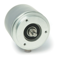
Mounting of the encoder
• Fixation either by screws or via torque pin and shaft
clamping. Ensure that the encoder is mounted
without strain and use torque pin.
• Forces must not be transmitted via the housing,
but only via the shaft.
• Do not exceed the values for the maximum axial
and radial shaft load.
• Ensure accurate shaft alignment. If shaft and
flange are not correctly aligned, strain on the
bearings will result, which will overheat and be
irreparably damaged.
4. Electrical connection
• Switch power o before any plug is inserted or
removed!
• Any wiring must only be carried out without power.
• Provide stranded wires with ferrules.
• Check all lines and connections before switching
on the equipment.
• The encoder's and follower electronic's (e. g.
control unit) operating supply must be switched
on simultaneously.
Safety precautions:
• If personal injury or damage to equipment is pos-
sible should the encoder fail or malfunction, this
must be prevented by suitable safety precautions
such as protective devices or limit switches, etc.,
or the device must be disabled and secured against
accidental switching on.
Interference and distortion
All connections are protected against the eects of
interference. The location should be selected to
ensure that no capacitive or inductive interfe-
rences can aect the encoder or the connection
lines! Suitable wiring layout and choice of cable
can minimise the eects of interference (e. g. in-
terference caused by SMPS, motors, cyclic controls
and contactors).
Although the angle encoder is suciently pro-
tected from external magnetic fields, it is not re-
commended to use it quite close to strong magnetic
fields (e. g., magnetic brakes, magnetic clamps)!
Necessary measures
• Only use shielded cables. Wire cross section is to
be at least 0,14 mm², max. 0,5 mm².
• Wiring to the screen and ground (GND) must be
secured to a good point.
• The system should be positioned well away from
cables with interference; if necessary a protective
screen or metal housing must be provided. The
running of wiring parallel to the mains supply
should be avoided.
• Contactor coils must be linked with spark sup-
pression.
Power supply
Supply voltage depends on the unit type and is in-
dicated in the delivery documentation and on the
identification plate.
12 ... 30 V d.c. (current output)
15 ... 30 V d.c. (voltage output)
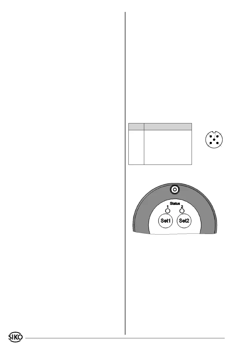
4.1 Connection
5 pole plug pin.
Pin Designation
1 Iout/Uout
2 +UB
3 GND
4 Set 1
5 Set 2
5. Commissioning
5.1 Function of alignment
Start the programming mode by simultaneously
pressing both keys for approx. 15 seconds up to
max. 20 seconds. The keys’ function is also given
by activating the relevant set inputs (Uin > 12 V;
Uin ≤ UB), see chapter 4.1. The minimum range of
measurement is 22.5°:
1. Turn shaft to the smallest position
2. Press Set 1 key for one second.
3. Turn shaft to the largest position.
4. Press Set 2 key for one second.
Now, the analog output is aligned to the new
measuring length.
 Loading...