MA10/4
Installation English
MA10/4 · Date 15.05.2017 · Art. No. 82316 · Mod. status 157/17
19
Connection
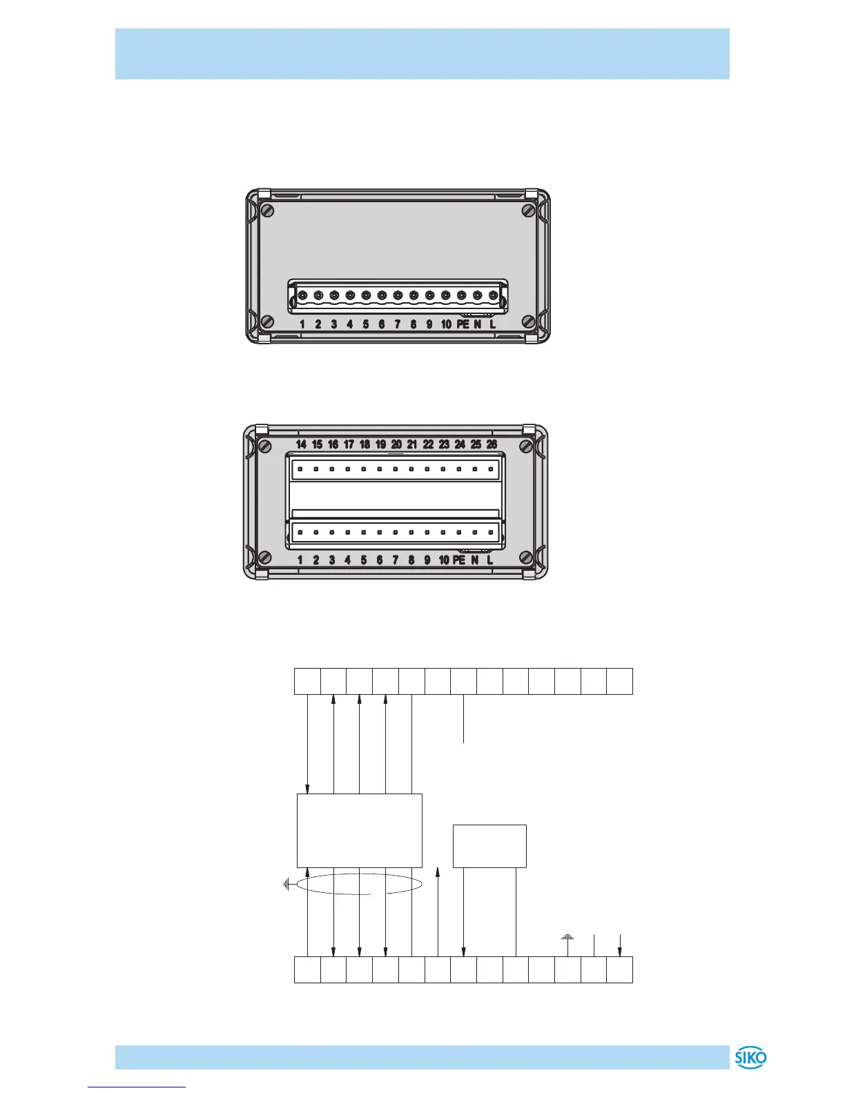
• 1x 13 pin coupler strip (see Fig. 2).
• 2x 13 pin coupler strip (see Fig. 3).
Fig. 2: Pin outs (PP-, OC-output circuit, without interfaces and without
switching output) for incremental, speed, number of pieces
Fig. 3: Pin outs for options (LD-output circuit, interfaces, switching
output) for incremental, absolute, speed, number of pieces
Fig. 4: Connection diagram incremental
encoder
supply
A-Signal
B-Signal
Index-Signal
GND
24VDC out ≤50mA
RFS
GND
PE
N (0V)
L (+UB)
GND
GND
encoder supply
≤200mA
/A-Signal (LD,OP)
/B-Signal (LD,OP)
/Index-Signal (LD,OP)
screen
incremental encoder
LD (Line-Driver)
PP (push-pull)
OC (open collector)
OP (push pull)
reference
switch
 Loading...