IM_FULL_65SL_REV-A 7
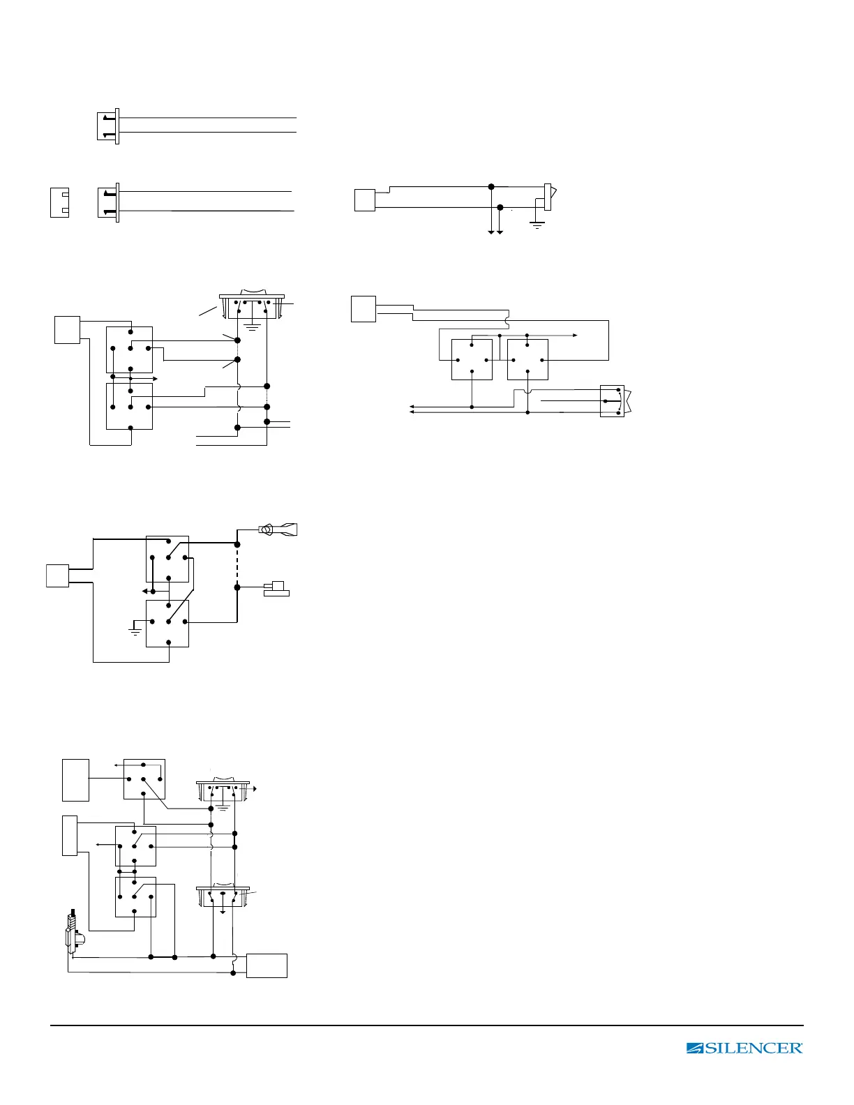
3 PIN, DOOR LOCK CONNECTOR ( 500 mA OUTPUT )
VACUUM OPERATED DOOR
LOCKING SYSTEM:
TYPICAL OF MERCEDES BENZ
AND AUDI.
Locate the wire under the driver’s kick panel.
Use the voltmeter connecting to ground, verify
that you have the correct wire with the doors
unlocked, the voltmeter will receive “12 volts”.
Lock the doors and the voltmeter will read “0 volt”.
Move the alligator clip to +12V and the voltmeter
will receive “12 volts”. Cut this wire and make
connections. Be sure to program door lock timer
to 3.5 seconds.
1. Blue Wire
3. Green Wire
( - ) Lock Pulse
( - ) Unlock Pulse
Blue Wire
Green Wire ( + ) Unlock Pulse
( - ) Unlock Pulse
NEGATIVE TRIGGER DOOR LOCK SYSTEM
Blue Wire Door Unlock
Green Wire Door Lock
Locking
Master
Switch
To Exiting
Door Lock Relay
Cut the Existing
Lock Wire
Cut the Existing
Unlock Wire
5-WIRE ALTERNATING DOOR LOCK
POSITIVE TRIGGER DOOR LOCK SYSTEM
(+) Lock Out
+12 Volts Input
(+) Unlock Out
To Door Lock
Control Relays
Blue Wire: Connect to Unlock
Green Wire: Connect to Lock
Lock Control
Switch
3 Pin Plug
to Alarm
87
87A
85 86
30
87
87A
85 86
30
To Fused +12v
ACUUM OPERATED CENTRAL LOCKING
Green Wire
Blue Wire
+12V
X
Cut
Compressor
Door Switch
30
86
87a
85
87
30
86
87a
85
87
3 Pin
Plug To
2 STEP DOOR UNLOCK WIRE CONNECTION FOR
5 WIRE ALTERNATING DOOR LOCKS
+12V
Cut the Existing
Lock Wire
Cut Existing Unlock
Cut the Unlock Wire
Lock
Unlock
OEM Door Master Lock
OEM Slave
Door Lock
Switch
+12V
Lock Unlock
To All Other
Door Lock
Motors
22-Pin
Plug
From
Alarm
Pink Wire
x
X
Blue Wire
OEM Driver’s
Door Lock Motor
+ 12V
85
86
87
87a
30
30
87
85
87a
86
30
87
85
87a
86
Green Wire
3 Pin
Plug
To
Alarm
Red +12V