IM_FULL_65SL_REV-A 9
WHITE / BLACK WIRE – NEGATIVE SAFETY SHUT DOWN INPUT & HOOD TRIGGER
The White Black provides an instant shutdown
for the remote start, whenever it is grounded.
Connect the wire to the hood pin switch
previously installed. This wire must be routed
though a grommet in the rewall and connected
to the hood pin switch. If the pin switch is to be
used with an alarm system, connect this wire
with diode.
Important! This connection is a safety wire and must be connected as shown and tested as speciled. Failure to do so
may result in personal injury or property damage. See detail of wiring in the above diagram. This wire may also be used
if the vehicle brake light circuit switches ground to the brake lights. An isolation diode must be used for ground switched
brake light circuits and must be connected to the output of the brake switch.
YELLOW WIRE – (-) 200MA IGNITION 3 OUTPUT –
This wire provides a 200mA (-) ground output that becomes active 2 seconds before the remote start unit initializes and
remains grounded while running.
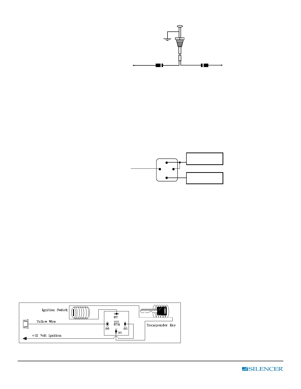
IGNITION 3 OUTPUT:
Some newer vehicles use a third ignition wire
which is required to start and keep the vehicle’s
engine running. If this is the case, wire an IGN
3 relay (not supplied) as shown: Do not connect
any vehicle circuits together, they are isolated for
a reason.
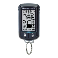
TRANSPONDER INTERFACING USING RELAY:
If the vehicle has a transponder system installed, you will need to by-pass the system
while the vehicle is operating under the control of the Remote Start Unit.
To do this:
1. You will need a transponder key that’s already programmed to the vehicle.
2. Remove the trim around the ignition switch.
3. Wrap a thin (28 - 30awg) wire tightly around ignition switch 6 to 8 times and secure it.
4. About 6” down line make another loop of approximately 2” diameter.
5. Place the key inside this loop and secure it to the loop.
1. Connect an end of the (28 - 30awg) wire to pin (87) of the relay module.
2. Connect the other end of the loop wire to Pin (30) of relay module.
3. Connect the pin (86) of the relay module to the ignition wire from the ignition switch.
4. Connect the pin (85) of the relay module to the yellow wire of 20-pin connector.
To: White/black wire /
Negative safety
To: Alarm instant
trigger Blue wire
Ignition 3 Wire From
Ignition Key Switch
+ 12 V Constant
Fused 25A Capable