76
4. Now attach the installation frame by bending the installation brackets towards the outside with a screwdriver. The frame is
properly installed when it can no longer be pulled out, yet also keeps from sliding further into the installation slot.
5. Now connect the cable set and the antenna corresponding to Abb. 8.3 and Abb. 8.4 as well as the table below to the
vehicle’s electric system. Also observe the specifications in sections 8.2 to 8.4.
Contact
Connector pin assignment ISO connector plug (also see Abb. 8.3 number 7)
Plug A Plug B
1 Rear right (+)
purple
2 Rear right (-) - purple / black
3 Front right (+) - grey
4 Ignition (ACC+) / red Front right (-) – grey / black
5 Car antenna / blue Front left (+) - white
6 Automatic operating panel dimmer / orange Front left (-)
white / black
7 Battery 12V (+) / yello
Rear left (+) - green
8 Ground / black Rear left (-)
green / black
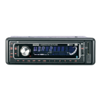
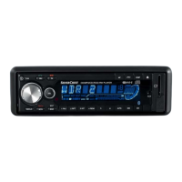
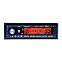
6. Slide the device into the installation frame as far as the stop point. You will hear the device audibly lock into place.
7. Attach the front frame and then insert the operating panel.
 Loading...