42C System Operations - 15
ELECTRICAL SYSTEM
This section describes the various com-
ponents of the Electrical System on your
42C. Also included is a Troubleshooting
Guide for your convenience.
AC/DC PANEL
The AC/DC Panel is where all the controls
for the electrical system are located. The
panel is broken down into three main sec-
tions. The top part of the panel, labeled
12 Volt DC Controls, is the controls for the
electrical system when it runs on batteries.
The lower part of the panel, labeled 240
Volt AC Controls, is the controls for when
the electrical system runs on AC.
DC ELECTRICAL SYSTEM
Located in the engine compartment, the
DC Electrical System obtains its source
of power from the batteries. The nega-
tive terminal of each battery is attached
to a grounding stud on each engine. This
is known as a “negative ground system”
and is the approved system for marine
DC electrical systems. The battery wiring
system has two color-coded wires. The
yellow wire is the ground (negative) wire
and the red wire is the positive (hot) wire.
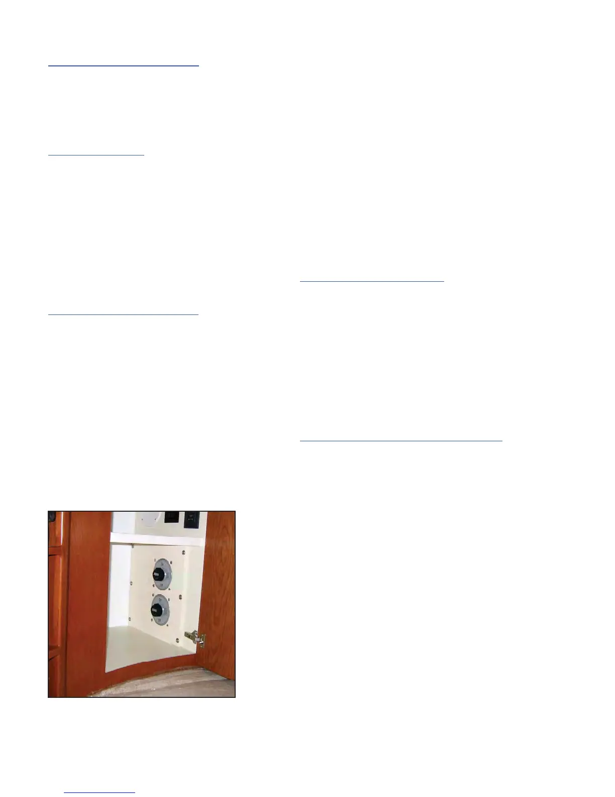
Both batteries are connected to a battery
switch (See photograph below).
The positions on the battery switch are ON
and OFF. The switch must be turned to
the ON position to supply power to the DC
electrical system. When the battery switch
is turned to the OFF position, power is
disconnected to the DC electrical system.
NOTE: The bilge pumps, carbon monox-
ide detectors, and radio memory are NOT
disconnected from their power source
when the battery switch is turned to the
OFF position. These accessories are con-
nected directly to the battery and do not
require a switch for operation.
Battery Charging System
The batteries maintain their charge from
alternators, which are located on each
engine. The alternators supply charg-
ing power to the batteries only while the
engines are running. Your 42C also has
a converter, located in the bilge, which
converts 120 volt AC electrical power from
either the generator or shore power into
12 Volt DC electrical power.
Activating the DC POWER SYSTEM
There are three (3) sets of switches that
must be in the ON position to activate the
DC Power to your 42C. One set of switch-
es is on the ship service box down in the
engine room. These switches are normally
in the ON position. The second set of
switches would be the battery switches, lo-
cated under the access panel on the steps
going from the Salon to the Passage-
way/Galley. The third set would be on the
AC/DC Panel. On the top portion of the
AC/DC Panel are two rows of switches.
The very top switches on the top of each
row are the Main Battery Switches. Each
switch controls that row of switches below
it. To supply power to one of the switches
listed on the left side of the panel, the top
switch on the left hand side must be on.