SYSTEM OPERATIONS-14
Key Switch for the Port Engine.
”Main Battery 1” breaker on the DC
Electrical Panel.
”Flybridge Electric” breaker on the DC
Electrical Panel.
Auto/Bilge Memory Breaker Switch - The
Auto/Bilge Breaker Switch gets its’ power
from the Port Battery Bank. The power
goes from this switch to the following loca-
tions:
The AUTO Bilge switches on the DC
Electrical Panel.
The Constant ON section of the Fuse
Box behind the Electrical Panels.
The Port and Starboard Battery Switches
control just about all appliances of the en-
tire DC System. If the switches are OFF,
no DC power at all is activated on your
boat. The items that the Battery Switches
do NOT turn off are the memory fuse box,
Engine Controls, Windlass, and Automatic
Bilge Pump Switches. The Engine Con-
trols and the Windlass each have their
own Breaker that turns off the DC Power.
NOTE: The bilge pumps, carbon monox-
ide detectors, radio memory, Windlass,
and Engine Controls are NOT discon-
nected from their power source when the
battery switch is turned to the OFF posi-
tion. These accessories are connected
directly to the battery and have their own
Breaker Switch. To work on these items,
you would have to locate their breakers
and turn it OFF.
Generator Battery Switch: The Generator
Battery Switch is located starboard of the
generator in the engine room. This switch
determines if the battery power is ON or
OFF to the generator. The generator sup-
plies AC power, not DC Power.
•
•
•
•
•
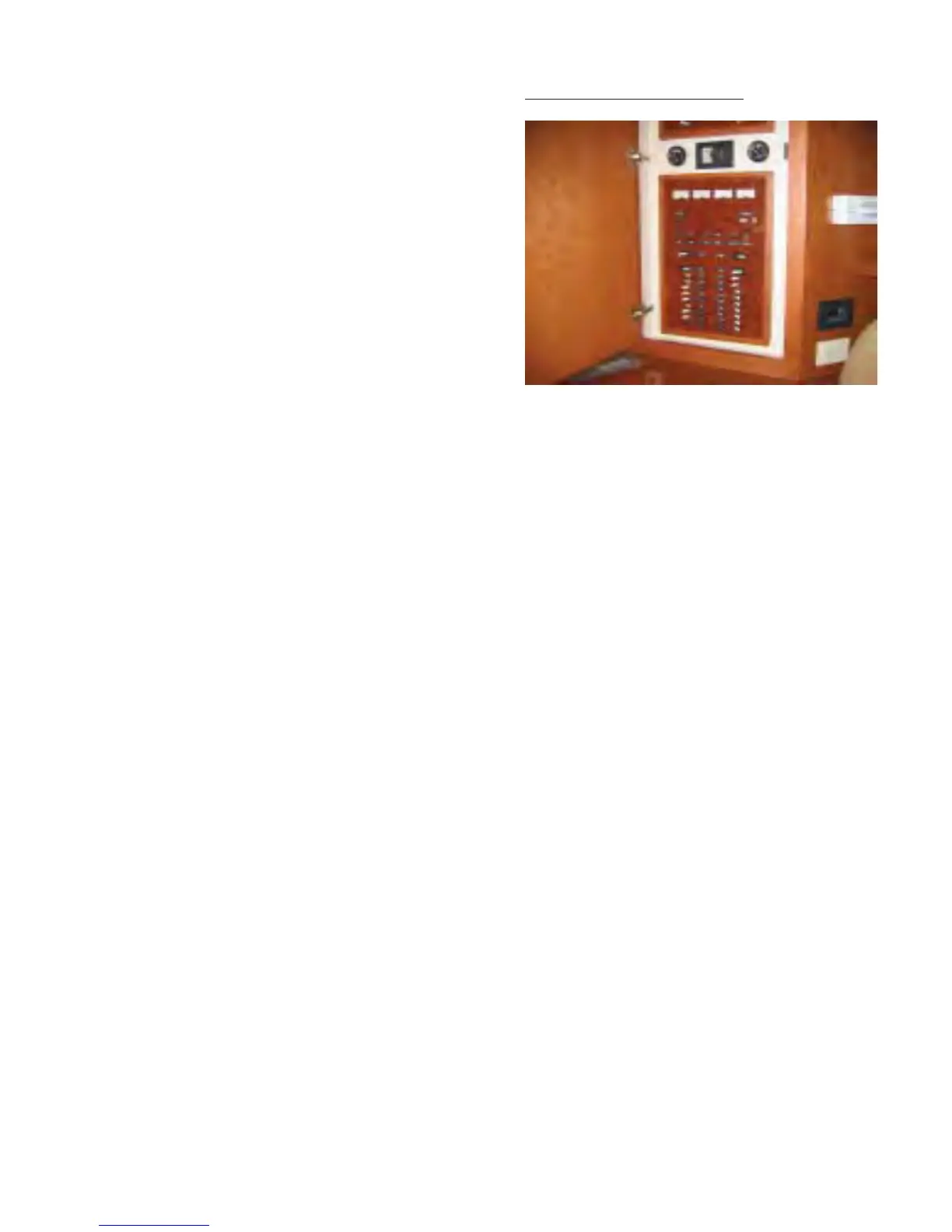
DC ELECTRICAL PANEL
The DC Electrical Panel can be broken
down into fi ve sections:
Meters at top of Panel.
Generator Start Switch and Blower
Switch. Directly below the Meters.
Auto Bilge Switches. Directly below the
Generator Switches.
Flybridge Switches. Directly below the
Auto Bilge Switches.
Main Breaker Section. The remaining
breakers at the bottom of the panel.
1. The DC Meters - At the very top of
the panel are three (3) meters. The two
(2) meters on the left read the Port Battery
Bank. The two (2) meters on the right read
the Starboard battery bank. Each set of
meters read the amperage and the volt-
age supplied by the batteries.
2. Generator Start Switch and Blower
Switch - Directly under the four (4) meters
are two (2) switches. One switch is to start
and stop the generator. The other switch
is for the Blowers in the Engine Room.
1.
2.
3.
4.
5.