The Sim-Lab XP-1 Pedals are a high-performance sim-racing pedal set designed for serious enthusiasts, offering extensive customization and a realistic racing experience. This manual covers the XP-1 LC Pedal Set, which includes a loadcell brake and a clutch (sold separately).
Function Description:
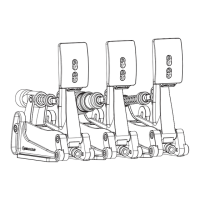
The XP-1 Pedals are engineered to simulate the feel of various car pedals, providing a comprehensive sim-racing experience. The set includes a brake pedal with a custom integrated 200KG loadcell, and throttle/clutch pedals equipped with Hall sensors for precise input. The pedals are designed for plug-and-play functionality via USB-B and offer 16-bit resolution input, ensuring high fidelity and responsiveness in sim-racing applications. The modular design allows for individual adjustment and replacement of components, catering to diverse preferences and racing styles.
Important Technical Specifications:
- Construction: Aluminum construction for durability and rigidity.
- Brake Pedal: Custom integrated 200KG loadcell for realistic braking force simulation.
- Throttle/Clutch Pedals: Hall sensors for smooth and accurate input.
- Resolution: 16-Bit resolution input for fine control.
- Connectivity: USB-B for plug-and-play operation.
- Elastomers: Multiple elastomers included with Shore A ratings: Soft (50A), Medium (60A - pre-installed), Hard (70A).
- Springs: Multiple springs included for throttle and preload adjustment.
- Pedal Base Adjustment: Approximately 20 degrees of angle adjustment for the pedal arm.
- Pedal Face Adjustment: Adjustable position and angle of the pedal face.
- Control Box: Mounting tabs suited to an 80x40 pattern, compatible with P1-X and X1-Pro cockpits.
- Cable Lengths: Pedal cable short (30cm), pedal cable long (75cm), USB-A cable (1 unit).
- Mounting Hardware (Throttle and Brake Set):
- Lock-Nut M6 (20 units)
- Lock-Nut M5 (2 units)
- Slot-Nut M6 (10 units)
- Slot-Nut M5 (4 units)
- Bolt M6 X 30 DIN 912 (10 units)
- Bolt M6 X 20 DIN 912 (10 units)
- Bolt M5 X 25 DIN 912 (2 units)
- Bolt M5 X 12 DIN 912 (4 units)
- Washer M6 DIN 125-A (20 units)
- Washer M5 DIN 9021 (2 units)
- Washer M5 DIN 125-A (4 units)
- Mounting Hardware (Clutch - sold separately):
- Bolt M6 X 30 DIN 912 (4 units)
- Bolt M6 X 20 DIN 912 (4 units)
- Washer M6 DIN 125-A (8 units)
- Lock-Nut M6 (4 units)
- Slot-Nut M6 (4 units)
Usage Features:
Installation:
The pedals can be mounted directly to profile-based pedal decks (like the P1-X) or GT1-EVO pedal decks, and are compatible with the latest universal baseplates. Mounting is achieved by bolting the set down using the 6mm slots on the underside of the pedals. For pedal slider baseplates, specific hardware (A11, A15, A18) is provided.
Configuration - Pedal Base:
The angle of the pedal arm relative to the cockpit can be adjusted. This involves loosening four bolts: two (P) where the arm pivots and two (A) in the arcs. Once loosened, the entire pedal can be rotated as a whole while the base remains fixed. A range of 20 degrees of adjustment is possible. It is crucial to tighten all bolts securely, especially for the brake pedal, to ensure stability under high forces.
Configuration - Pedal Face:
The position and angle of the pedal face are adjustable. Loosening the two bolts (F) holding the pedal face allows for position adjustment. To change the angle, loosen the top (T) countersunk bolts (do not remove them), then temporarily remove the bottom (B) bolts. The bracket can then rotate freely, offering preset slots for different angles. Once the desired angle is selected, fix it in place with the bottom (B) bolts, then tighten the upper (T) bolts.
Prepare for Changing Parts:
To access internal components for adjustment, the spring bolt (S) must be temporarily removed. This bolt connects the clevis fork to the pedal arm. Before removal, release any tension from the spring by loosening the adjustment knob(s). The spring bolt (S) can then be unclipped from the clevis fork shaft by rotating it upwards and pulling it away. This allows the shaft holding the parts to be turned away from the pedal arm, enabling component removal. Caution is advised as the pedal arm will be unsupported and can fall, potentially causing damage. It is recommended to hold or support the pedal arm during this process.
Throttle Configuration:
The throttle pedal offers two main adjustment options:
- Spring Stiffness: Unlock the blue locking knob (L) and tighten (clockwise) the adjustment knob (A) for a stiffer throttle feel, or loosen it for a softer feel. Once the desired stiffness is achieved, hold the adjustment knob (A) and tighten the locking knob (L) against it to secure the setting.
- Maximum Travel: On the bottom of the pedal arm, two blue knobs control travel. The inner knob is the locking knob (L), and the outer is the adjustment knob (A). Turning the adjustment knob clockwise reduces travel, while turning it anti-clockwise increases travel. The pedal is pre-set for a middle-of-the-road travel range, but users can experiment.
- Spring Force Adjustment Points: Beyond the adjustment knobs, the pedal arm has three adjustment points for the clevis fork. Using the lower point (S) results in a slightly softer pedal pressure, while the higher point (F) provides a slightly firmer feel.
- Mechanical Travel Limit: Due to the low position of the clevis fork on the pedal arm, mechanical travel might be limited. Users should manually check travel to ensure the clevis fork does not interfere with the flange on the pedal arm. If interference occurs, reduce maximum travel using the adjustment knobs until there is about 3-4mm clearance between the flat base of the clevis fork and the pedal arm flange.
- Heavy Throttle Spring: A heavy throttle spring is included for those seeking a firmer overall spring force range. This can be installed by following the steps for changing parts (page 7) and replacing the default spring.
Brake Configuration:
The brake pedal's configuration primarily involves changing internal parts. After following the steps for removing the clevis fork and shaft (page 7), components can be easily swapped.
- Components: The brake stack includes a Locking Knob (L), Adjustment Knob (A), Elastomer (E), Bushing (B), Elastomer Washer (W), and Pre-load Spring (P).
- Elastomers: Four elastomers with different Shore A hardness ratings are included: Soft (50A), Medium (60A - pre-installed), and Hard (70A). It is recommended to match maximum pressure to the elastomer rating, using lower pressures with the 50A elastomer to ensure durability.
- Preload Springs: Different preload springs are supplied to adjust the feel of the preload. The medium strength spring is pre-fitted.
- Preload Buffer: A preload buffer (BOM) is included to replace the spring if no preload is desired. This acts as a spacer. For no preload at all, the spring can be removed entirely, and the preload buffer will still function.
Clutch (Sold Separately) Configuration:
The clutch shares many base parts with the brake and throttle pedals, but includes an additional heavy spring. Travel is adjustable to a point.
- Adjustment Points: The clutch pedal is limited to using only the top adjustment point on the pedal arm due to its swiveling pivot part. Other adjustment holes are not supported.
- Maximum Travel: Maximum travel can be adjusted, but users should be aware that this may diminish the feel of the bite point.
- Spring Tension Adjustment: When adjusting the adjustment knob for spring tension, ensure that at full travel, it does not collide with the pivot. Small incremental adjustments are recommended to prevent damage.
Control Box:
- Installation: The control box features mounting tabs compatible with an 80x40 pattern, allowing it to be mounted almost anywhere near the pedals, typically underneath a profile-based pedal deck. M5 bolts should be tightened sufficiently but not overtightened.
- Connectivity: Cables from the pedals connect to the control box according to their labels. Cable management is recommended. All pedals use identical connectors, preventing mix-ups.
RaceDirector Software:
- Download: The latest version of RaceDirector can be downloaded from www.sim-lab.eu/srd-setup. A manual for installation and use is available at www.sim-lab.eu/srd-manual.
- Activation: To activate the XP-1 Pedals, navigate to the 'Settings' (1) page in RaceDirector, tick the 'Activate' checkbox next to 'XP-1 Pedals' (2). An icon (3) will then appear on the left side of the screen, leading to the device pages.
- Device Page: The device page allows for calibration (1), input curve adjustment (2), and deadzone adjustment (3).
- Calibration: Press 'Calibrate' (1), move the pedal to maximum travel or force, then press 'Finish calibration'.
- Deadzones: Dial in some deadzone (3) on both sides of the spectrum to prevent unwanted input. Percentages are based on the calibrated range, and single-digit values are recommended.
- Input Curve Adjustment: Input curves (2) can be adjusted by moving up to 5 points on a line. The 'input slider' (4) shows how the curve affects input.
- Profiles: Settings can be saved as profiles (5) and loaded (6). RaceDirector also includes default presets (7).
Maintenance Features:
The pedal set incorporates bronze bushings and Teflon parts, but regular cleaning and oiling are recommended to maintain performance and condition.
- Lubrication: WD-40 Specialist White Lithium Grease is recommended for lubricating moving parts.
- Spring Bolt: Do not forget to lubricate the spring bolt, which also sits in a bushing on the pedal arm.
Regular maintenance is quick and easy, contributing to the longevity and enjoyment of the pedal set.