Page 29
Page 29
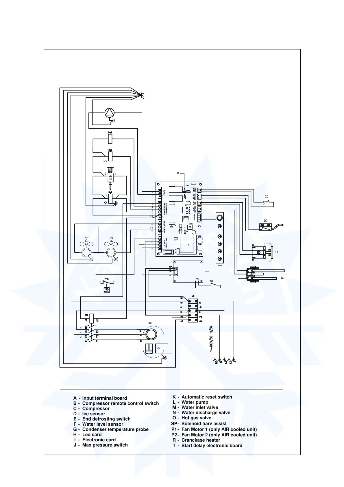
SV 545 - WIRING DIAGRAM
400 V. 50 Hz. 3 ph.
A - Input terminal board
B - Compressor remote control switch
C - Compressor
D - Ice sensor
E - End defrosting switch
F - Water level sensor
G - Condenser temperature probe
H - Led card
I - Electronic card
J - Max pressure switch
K - Automatic reset switch
L - Water pump
M - Water inlet valve
N - Water discharge valve
O - Hot gas valve
SP- Solenoid harv assist
P1- Fan Motor 1 (only AIR cooled unit)
P2- Fan Motor 2 (only AIR cooled unit)
R - Cranckase heater
T - Start delay electronic board
m = brown
bc = light blue
gv = yellow green
b = white
n = black
r = red
a = orange
v = viola
L
SP
F
E
G
v
v
bc
m
bc
n
b
r
a
m
n
bc
n
n
n
nm
bc
n
bc
n
v
v
N
b
bc
M
r
bc
D
n
m
P1
P2