EasyManua.ls Logo

SimCom SIM7000 Series

SimCom SIM7000 Series
12 pages
To Next Page IconTo Next Page
To Previous Page IconTo Previous Page
Loading...
Simplify Communication
SIM7000 Series EVB Quick Start Guide Page 8 / 12
Index
Position
Description
Index
Position
Description
E
J305
NC
F
J202
Main sim slot
O
S201
Power switch
G
J401
n/a
P
S401
RF switch
H
J204
USB-2-UART
Q
J203
sim slot (n/a)
I
J101 / J102
To TE board
R
J502
Handset jack
J
D402
Status LED
S
X501
Audio jack
K
D401
Network LED
T
J103
+5V DC input
L
D201
Power LED
U
TE_J105
LTE antenna SMA
M
SW401
PWRKEY
V
TE_J103
GNSS antenna SMA
N
SW402
Reset
W
TE_J102
USB interface
X
TE_U1
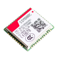
SIM7000 module
Y
TE_201/202
To EVB
Notice
1) Module GPIO pins are at 1.8V logical level. Can not be connected to external 3.0V or higher
level signals directly.
3 Installations and Communication
3.1 Driver installation
There have two USB jacks, one is on EVB board (USB-2-UART, position H), and another is on TE
board (position W).
3.1.1 USB-to-UART interface driver installation
This USB-to-UART chipset on board is from Silicon labs.
Here is the driver link.
https://www.silabs.com/products/development-tools/software/usb-to-uart-bridge-vcp-drivers
After driver installed properly and completely, there have two virtual USB ports, COM12 and
COM13.

Other manuals for SimCom SIM7000 Series

Related product manuals