Do you have a question about the SimCom SIM800 and is the answer not in the manual?
Lists key features of the SIM800 module, including power supply, power saving, frequency bands, and connectivity.
Describes the different operating modes of the SIM800 module, such as SLEEP, IDLE, TALK, STANDBY, DATA, Power off, and Minimum functionality.
Presents a functional block diagram illustrating the internal architecture and interfaces of the SIM800 module.
Provides a visual representation of the SIM800 module's pin layout, showing pin numbers and their general function.
Details the function, I/O type, and comments for each pin of the SIM800 module.
Shows the mechanical dimensions of the SIM800 module in millimeters, crucial for PCB design.
Details the power supply requirements, voltage range, current capacity, and recommended bypass capacitors and protection circuits for the SIM800 module.
Explains the Pulse-Width Modulation (PWM) interface, its capabilities, and pin definitions for controlling external devices.
Describes the NETLIGHT pin used for indicating network status, including its behavior in different network conditions.
Details the STATUS pin, which indicates the module's power status (on/off).
Covers the KPLED pin, an open-drain driver for keypad backlighting, including its specification.
Explains the RF_SYNC signal, used to indicate power consumption during transmit bursts, and its timing.
Discusses the GSM and Bluetooth antenna interfaces, impedance requirements, and placement recommendations.
Guides on understanding PIN assignments for effective PCB design and component placement.
Outlines key principles for PCB layout, focusing on critical interfaces like Antenna, power supply, and SIM card.
Provides specific guidelines for routing RF traces, antenna placement, and matching circuits for optimal performance.
Emphasizes the importance of proper power supply and ground layout, including Zener diode and capacitor placement.
Details layout considerations for the SIM card interface to prevent interference and ensure reliable operation.
Advises on routing audio traces to avoid noise and interference from other signals like RF and power.
Briefly mentions tracing UART and USB signal lines.
Defines the stress ratings beyond which permanent damage to the SIM800 module may occur.
Specifies the recommended operating voltage, temperature, and storage conditions for reliable module performance.
Details the electrical characteristics of digital interface pins, including input and output voltage levels.
Provides electrical specifications for the SIM card interface, covering input/output currents and voltages.
Lists the characteristics of the SIM_VDD power supply, including output voltage and current.
Outlines the characteristics of the VDD_EXT output, specifying voltage and current capabilities.
Details the characteristics of the VRTC pin, used for RTC backup power, including input/output voltages and currents.
Presents typical current consumption values for various operating modes and conditions at a specific VBAT level.
Highlights the SIM800's sensitivity to ESD and provides ESD test results for various pins.
Details conducted output power for different GSM/PCS bands, following 3GPP specifications.
Specifies the typical and maximum RF receive sensitivity for the module across different frequency bands.
Lists the operating frequency ranges for receiving and transmitting across GSM850, EGSM900, DCS1800, and PCS1900 bands.
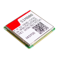
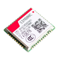
Shows visual representations of the top and bottom sides of the SIM800 module, highlighting markings.
Illustrates the standard temperature curve and parameter ranges for lead-free solder reflow processes.
Explains the moisture sensitivity level (MSL) of the SIM800 and the corresponding floor life conditions.
Provides guidelines for baking the SIM800 module to prevent moisture absorption and ensure proper soldering.
Describes the tray packaging method for the SIM800 module, including a diagram.
Details the dimensions and drawing of the small carton used for packaging.
Details the dimensions and drawing of the big carton used for packaging.
Lists related documents, including AT command manuals, GSM specifications, and application notes.
Provides a glossary of terms and abbreviations used throughout the document for clarity.
Outlines essential safety precautions for using the cellular terminal/mobile in various environments and situations.
| Frequency Bands | 850/900/1800/1900 MHz |
|---|---|
| GPRS Multi-slot Class | Class 12 |
| GPRS Mobile Station | GPRS Mobile Station Class B |
| Compliant to GSM Phase | 2/2+ |
| CSD Data Features | Up to 14.4 kbps |
| USSD | Supported |
| Supply Voltage Range | 3.4V to 4.4V |
| Operating Temperature | -40°C to +85°C |
| Transmitting Power | Class 4 (2W) @ 850/900 MHz, Class 1 (1W) @ 1800/1900 MHz |
| SMS | Text and PDU mode, point-to-point MO and MT, SMS cell broadcast |
| Interfaces | UART, GPIO, ADC, I2C, SPI |
| Dimensions | 24 x 24 x 3 mm |
| TCP/IP | Supported |
| Voice | Supported |


