Smart Machine Smart Decision
SIM800_Hardware Design_V1.10 22 2018-08-13
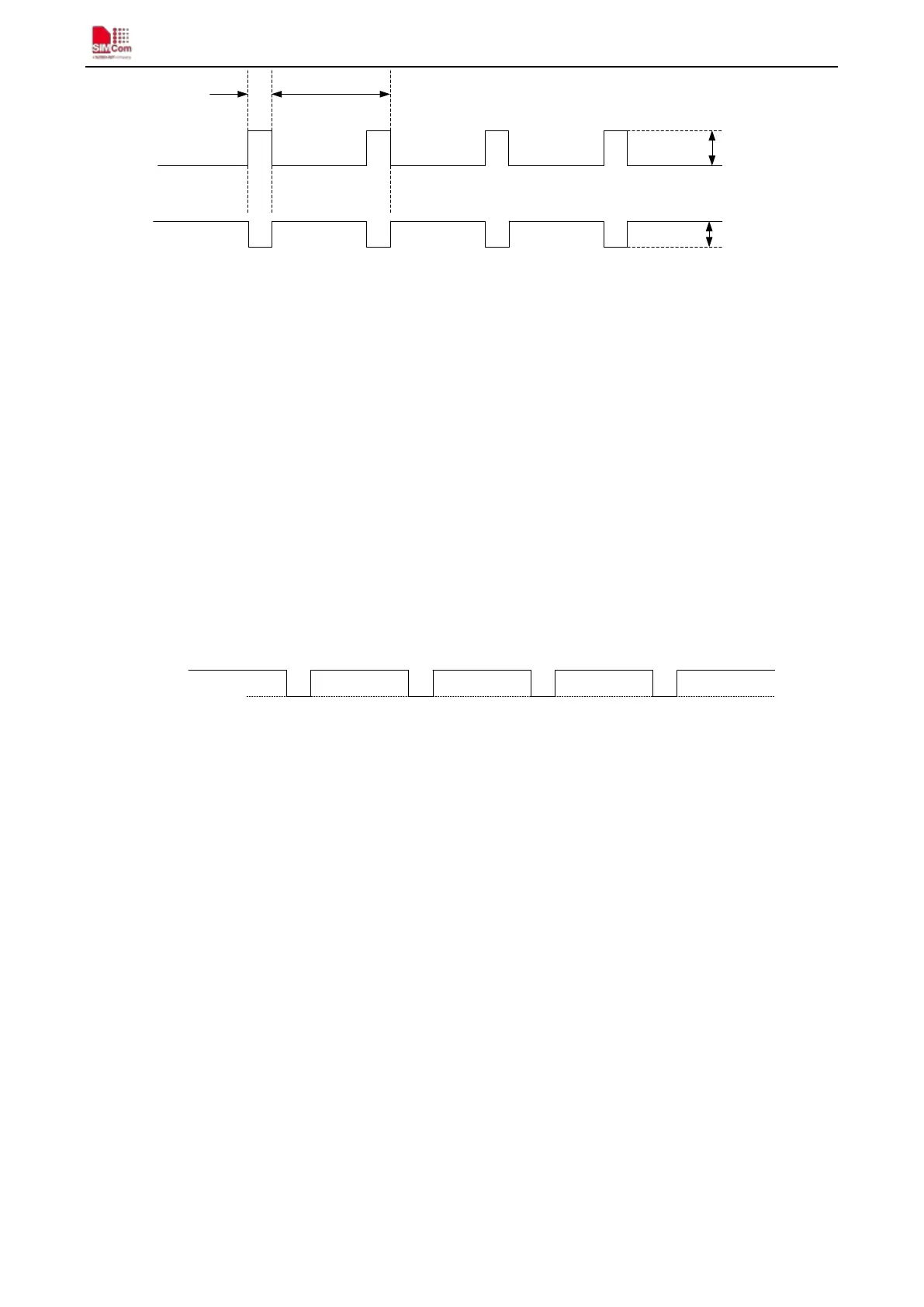
577us 4.615ms
I
VBAT
VBAT
Max:350mV
Burst:2A
Figure 8: VBAT voltage drop during transmit burst
4.1.1. Power Supply Pin
The VBAT pins are used for power input, and pin 62,63,64,65 should be connected to the power GND. VRTC
pin is power supply of the RTC circuit in the module. VDD_EXT will output 2.8V when module powered up.
When designing the power supply in user’s application, pay special attention to power losses. Ensure that the
input voltage never drop below 3.4V even when current consumption rises to 2A in the transmit burst. If the
power voltage drops below 3.4V, the module may be shut down automatically. The PCB traces from the VBAT
pins to the power supply must be wide enough (at least 80mil) to decrease voltage drops in the transmit burst. The
power IC and the bypass capacitor should be placed to the module as close as possible.
Figure 9: The minimal VBAT voltage requirement at VBAT drop
Note: Hardware Power down voltage is 3.0V.
4.1.2. Monitoring Power Supply
The AT command “AT+CBC” can be used to monitor the VBAT voltage. For details please refer to document
[1].
4.2. Power on/off SIM800
4.2.1. Power on SIM800
User can power on SIM800 by pulling down the PWRKEY pin at least 1.2 second and then release. This pin is
already pulled up to VBAT in the module internal, so external pull up is not necessary. Reference circuit is shown
as below.