Smart Machine Smart Decision
SIM800_Hardware Design_V1.10 33 2018-08-13
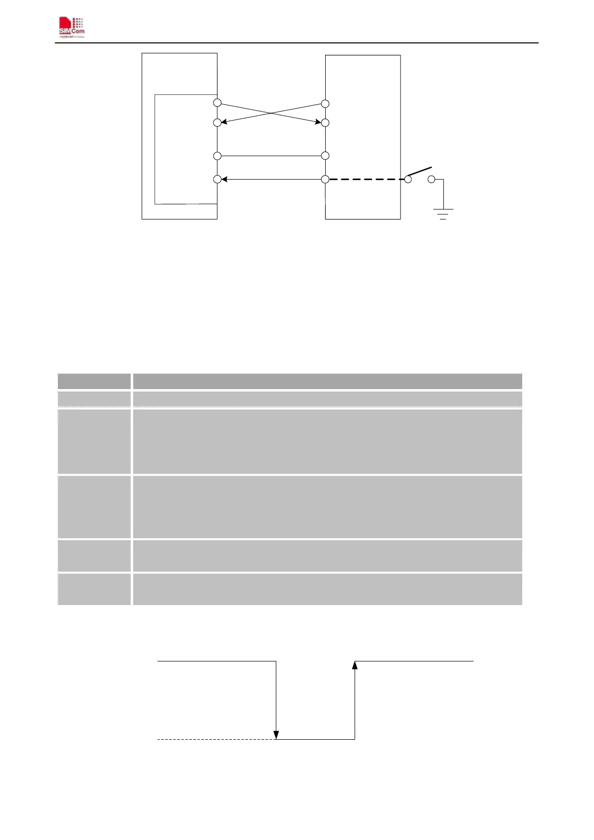
UART1_TXD
Module(DCE)
UART1_RXD
GND
PWRKEY
TXD
RXD
GND
Serial Port
PWRKEY
I/O Connector
Figure 25: Connection for software upgrading
The serial port supports the CMOS level. If user connects the module to the computer, the level shifter should be
added between the DCE and DTE.
4.6. RI Behaviors
Table 11: RI Behaviors
State RI response
Standby High
Voice call
The pin is changed to low. When any of the following events occur, the pin will be
changed to high:
(1)Establish the call
(2)Hang up the call
Data call
The pin is changed to low. When any of the following events occur, the pin will be
changed to high:
(1)Establish the call
(2)Hang up the call
SMS
The pin is changed to low, and kept low for 120ms when a SMS is received. Then it is
changed to high.
URC
The pin is changed to low, and kept low for 120ms when some URCs are reported. Then it
is changed to high. For more details, please refer to document [10].
The behavior of the RI pin is shown in the following figure when the module is used as a receiver.
HIGH
LOW
Idle Ring
Hang up the call
Establish the call
RI
Figure 26: RI behaviour of voice calling as a receiver