Smart Machine Smart Decision
SIM800_Hardware Design_V1.10 49 2018-08-13
There are two antenna ports for SIM800, GSM antenna port named GSM_ANT and Bluetooth antenna port
named BT_ANT; The RF interfaces of the two antenna ports both have the impedance of 50Ω
The input impendence of the antenna should be 50Ω, and the VSWR should be less than 2.
It is recommended that GSM antenna and Bluetooth antenna be placed as far as better.
The isolations of the two antenna should be more than 30db
NOTE: About the RF trace layout please refer to “AN_SMT Module_RF_Reference Design_Guide”
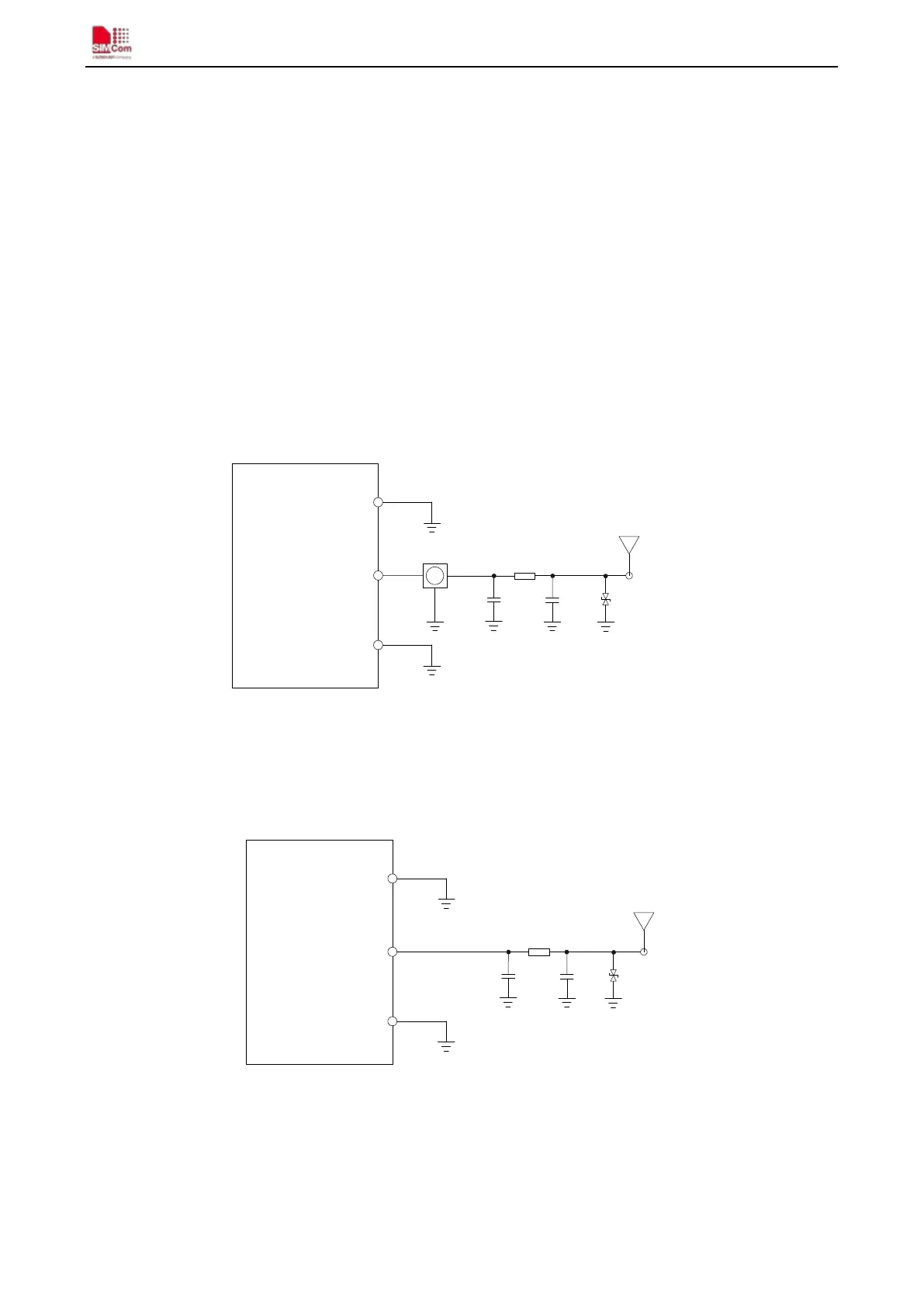
4.20.1. GSM Antenna Interface
There is a GSM antenna pad named GSM_ANT to connect a GSM antenna, the connection of the antenna must
be decoupled from DC voltage. This is necessary because the antenna connector is DC coupled to ground via an
inductor for ESD protection. The GSM antenna must be matched properly to achieve the best performance, so
the matching circuit is necessary. For the purpose of static electricity, we recommend to add D101, which is a
TVS, the recommendation ESD component as table 38. The connection is recommended as following:
GND
(Pin3)
R101
C101
C102
GND
(Pin1)
GSM
ANT
Module
connector
GSM_ANT
(Pin2
)
D101
Figure 46: GSM antenna matching circuit
R101, C101, C102 are the matching circuit, the values depend on antenna debug result. Normally R101 is 0Ω,
C101 and C102 are not mounted. The RF connector is used for conducted test. If the space between GSM_ANT
pin and antenna is not enough, the matching circuit could be simplified as the following figure:
R101
GSM_ANT
(Pin2)
C101
C102
GND
(Pin3)
GND
(Pin1)
GSM
ANT
Moule
D101
Figure 47: GSM simple antenna matching circuit
For the purpose of static electricity, we recommend to add D101, which is a TVS, the recommendation ESD
component as table 38.
Normally R101 is 0Ω; C101 and C102 are not mounted.