Smart Machine Smart Decision
SIM800_Hardware Design_V1.10 46 2018-08-13
output period and for the duty cycle. The AT command “AT + SPWM” is used to set the output period and duty
cycle of the PWM. For details, please refer to document [1].
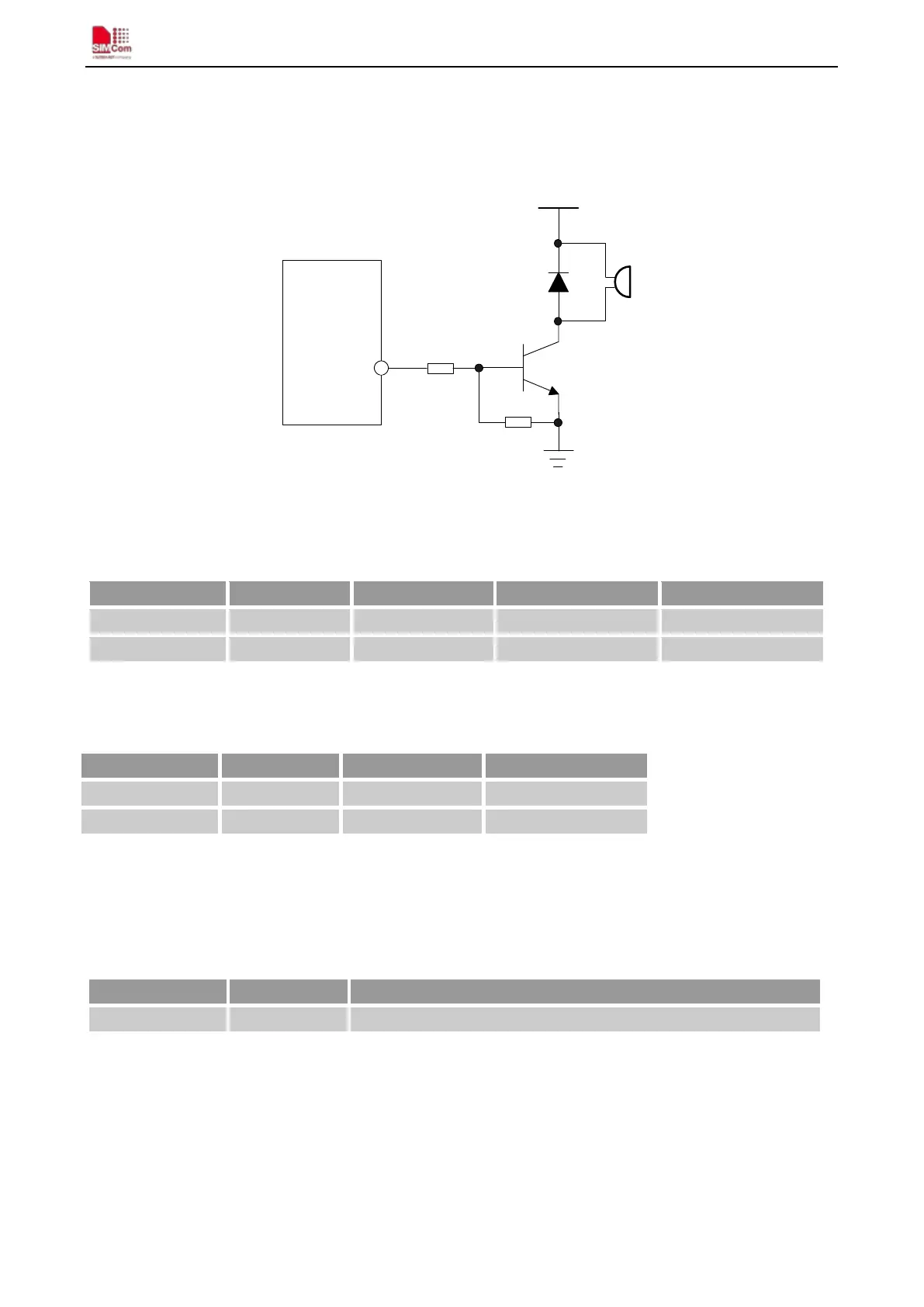
A typical circuit of the PWM drives buzzer is shown in the following figure:
Figure 42: Reference circuit of PWM drive buzzer
Table 26: PWM output characteristics
Parameter Min Typ Max Unit
Working voltage 2.5 2.8 2.9 V
Note: PWM pin must keep low when module in the boot process.
Table 27: PWM multiplex function
Pin name Pin number Mode 0(default) Mode 1
PWM0 35 PWM0 GPIO
4.16. Network Status Indication
Table 28: Pin definition of the NETLIGHT
The NETLIGHT pin can be used to drive a network status indication LED. The status of this pin is listed in
following table:
Table 29: Status of the NETLIGHT pin
NETLIGHT 52
Network Status Indication