Smart Machine Smart Decision
SIM800_Hardware Design_V1.10 45 2018-08-13
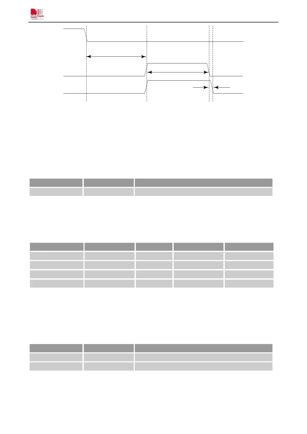
PWRKEY
(INPUT)
GPIO17
t<1.9s
GPIO19
t<=10us
t<1.9s
Figure 41: GPIO timing sequences
4.14. ADC
Table 23: Pin definition of the ADC
SIM800 provides an auxiliary ADC, which can be used to measure the voltage. Customerr can use AT command
“AT+CADC” to read the voltage value. For details of this AT command, please refer to document [1].
Table 24: ADC specification
Parameter Min Typ Max Unit
Voltage range 0 - 2.8 V
ADC Resolution - 10 - bits
Sampling rate - - 1.0833 MHz
Note: the voltage should less than 2.8V, or the ADC may be damaged.
4.15. PWM
Table 25: Pin definition of the PWM
Note: SIM800 can only support 1 PWM synchronously, if customer set PIN 35 as PWM, so PIN36 can only be
used as GPIO.
PWM output frequency varies from 200Hz – 100KHz.Two 7-bit unsigned binary parameters are used for the
Pin name Pin number Description
ADC 25 Analog to Digital Converter
Pin name Pin number Description