Smart Machine Smart Decision
SIM800_Hardware Design_V1.10 48 2018-08-13
Figure 44: KPLED driver reference circuit
Table 32: KPLED specification
4.19. RF Synchronization Signal
The synchronization signal serves to indicate growing power consumption during the transmit burst.
Table 33: Definition of the RF_SYNC pin
Note: Do not pull up RF_SYNC.
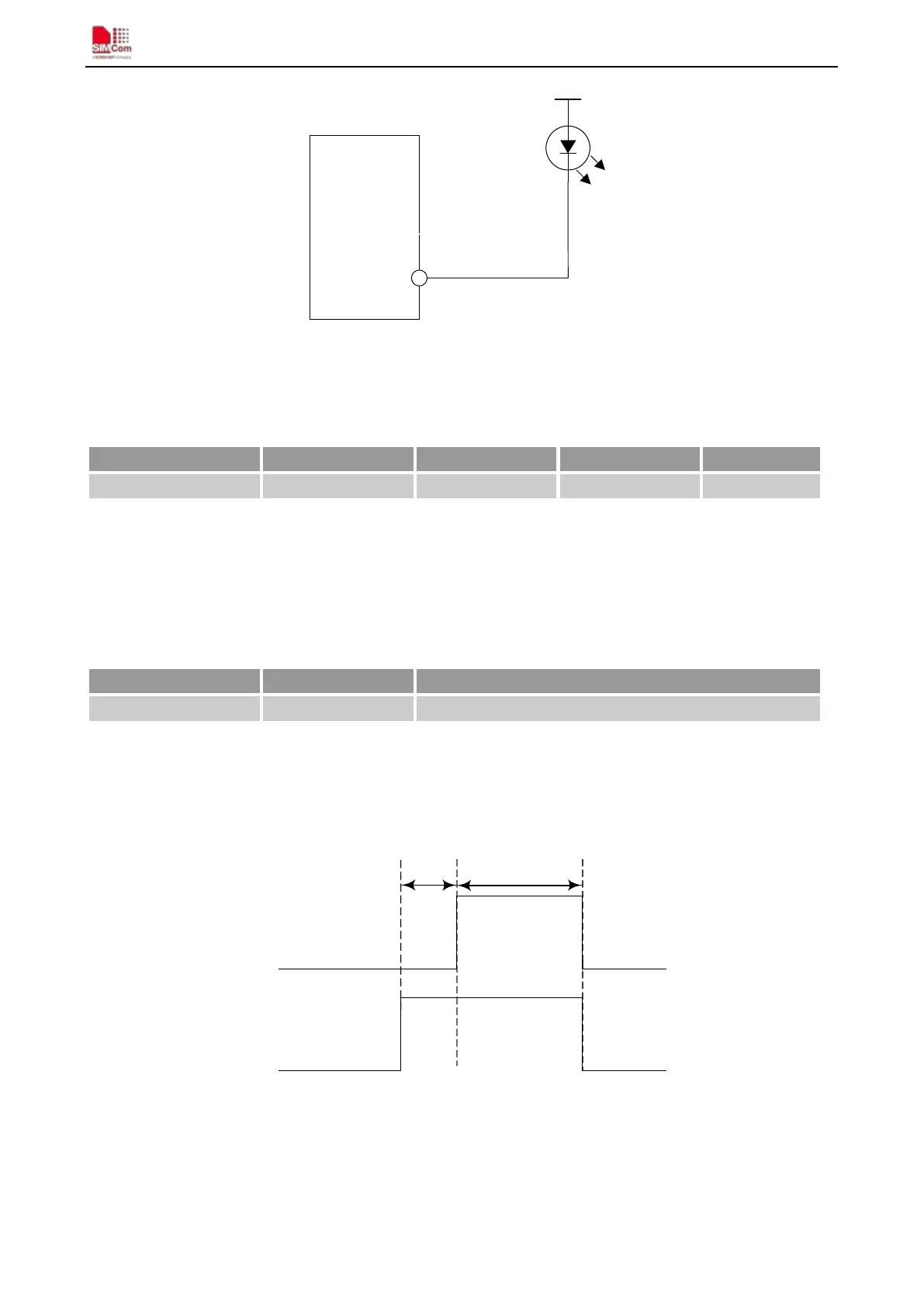
The timing of the synchronization signal is shown in the following figure. High level of the RF_SYNC signal
indicates increased power consumption during transmission.
Transmit burst
RF_SYNC
577us
220us
Figure 45: RF_SYNC signal during transmit burst
4.20. Antenna Interface
Pin name Min Typ Max Unit
KPLED - 60 mA
Pin name Pin number Description
RF_SYNC 67 Transmit synchronization signal