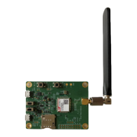
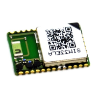
The SIMCom SIM7022-EVB is an evaluation board designed to help developers quickly become familiar with and verify the software functions of the SIM7022 NB Module. This user guide provides an introduction to the board's interfaces, technical specifications, and operation methods.
Function Description
The SIM7022-EVB serves as a development kit for the SIM7022 NB Module. It provides various interfaces and features to facilitate module testing, AT command communication, data transmission, firmware upgrades, and debugging. The board integrates power supply, (U)SIM card interface, UART interfaces, status indicators, switches, and test points to offer a comprehensive development environment.
Important Technical Specifications
Power Supply:
- USB_VBUS: 5V power supply.
- Module Power Supply: The recommended power supply range for the module is 2.2V to 4.2V. For separate power supply, the resistance R112 should be removed, and power supplied externally to the VBAT and GND test points. The power supply voltage is lower than 3V, and the radio frequency can work, but the performance of a single index may not meet the 3GPP standard.
SIM Card Interface:
- (U)SIM card: Supports dual voltage 1.8V/3.0V.
- Pin Definition (J102):
- Pin 1 (VCC): (U)SIM power supply (Output).
- Pin 2 (RST): (U)SIM reset signal (Output).
- Pin 3 (CLK): (U)SIM clock signal (Output).
- Pin 4 (DET): (U)SIM detect signal (Input).
- Pin 5 (GND): Ground.
- Pin 6 (VPP): Float.
- Pin 7 (I/O): (U)SIM duplex data line (Input/Output).
- Usage Note: The SIM card is inserted at position "J" on the EVB. The module does not support hot-swappable functionality. It is crucial to insert the SIM card before powering on the module; otherwise, the SIM card may not be recognized successfully.
UART Interface:
- The EVB provides two USB-to-UART interfaces:
- J103 (Main Serial Port): Used for AT commands, data transmission, and firmware upgrades.
- J104 (System Log Port): Used for software DEBUG debugging.
- Micro USB Interface Pin Definition (J103):
- Pin 1 (VBUS): USB power supply (Output).
- Pin 2 (USB_DM): USB differential data negative (USB-to-UART) (Input/Output).
- Pin 3 (USB_DP): USB differential data positive (USB-to-UART) (Input/Output).
- Pin 4: Float.
- Pin 5 (GND): Ground.
- UART Frame Format:
- Data bits: 8.
- Stop bits: 1.
- Parity: None.
- Flow control: None.
- UART Baud Rate Support:
- Fixed baud rates: 1200, 2400, 4800, 9600, 19200, 38400, 57600, 115200, 230400, 460800, 921600, 3200000.
- Auto baud rate detection is supported.
- Common Baud Rate Operations:
AT+IPR=x: Sets the baud rate to x.AT+IPR=0: Enables auto baud rate detection.
Status Indicator Lights:
- LED101 (Blue): Module network status indicator light.
- LED102 (Red): VBAT power supply indicator light.
- LED103 (Blue): Module power-on status indicator light.
Switches and Buttons:
- SW101 (Power Supply Switch): Controls the power supply to the module.
- SW1 (Firmware Upgrade Switch): Used for firmware upgrade operations.
- SW102 (RESET Button): Resets the module.
- SW103 (WAKEUP Button): Wakes up the module.
Test Points:
- J101: General test points for various signals.
- J105: Power test point.
- J106: Module signal test point.
- J107: Module signal test point.
Usage Features
Evaluation Kit Contents:
The SIM7022 Evaluation Kit includes:
- SIM7022-EVB board.
- MICRO USB data cable.
- GSM/WCDMA/LTE antenna.
It is recommended to use the correct kit model (8EC000-SIM7022-EVBKIT, Part No: S2-109DE) to ensure normal module operation.
Module Boot and Power-on Operation:
- Powering On:
- Ensure the SIM card is inserted correctly.
- Connect the antenna to the main antenna connector (H).
- Connect the USB cable to the J103 interface.
- Set SW101 to the ON position.
- Press the SW103 (WAKEUP) button for at least 100ms.
- The LED103 (Power-on status indicator) will light up, indicating successful power-on.
- Powering Off:
- Press the SW103 (WAKEUP) button for at least 100ms.
- The LED103 will turn off, indicating successful power-off.
- Resetting: Press the SW102 (RESET) button to reset the module.
Driver Installation:
- USB-to-UART Driver: The EVB uses a USB-to-UART chip (e.g., CP2102) to convert USB signals to UART. Drivers for this chip are typically available from the chip manufacturer's website.
- Installation Steps:
- Connect the EVB to the PC via the USB cable.
- Open Device Manager on the PC.
- Locate the unrecognized device (e.g., "CP2102 USB to UART Bridge Controller").
- Right-click and select "Update driver software."
- Browse for the driver software on your computer.
- Select the appropriate driver file (e.g.,
CP210xVCPInstaller_x64.exe for 64-bit systems).
- Follow the on-screen instructions to complete the installation.
- After successful installation, two new COM ports will appear in Device Manager (e.g., "CP2102 USB to UART Bridge Controller (COMx)" and "CP2102 USB to UART Bridge Controller (COMy)"). These correspond to the main serial port (J103) and the system log port (J104).
Firmware Upgrade Process:
- Preparation:
- Ensure the module is powered off.
- Connect the EVB to the PC via the USB cable (J103).
- Open the firmware upgrade tool (e.g., "SIMCom_DownloadTool").
- Select the correct COM port for the main serial port (J103).
- Load the firmware package (e.g.,
.pac file).
- Upgrade Steps:
- Set SW1 to the "Download" position.
- Set SW101 to the "ON" position.
- The download tool should detect the module and start the upgrade process automatically.
- Monitor the progress in the download tool.
- Once the download is complete, the tool will indicate success.
- Set SW1 to the "Run" position.
- Set SW101 to the "OFF" position, then back to "ON" to restart the module with the new firmware.
AT Command Communication:
- Setup:
- Ensure the module is powered on.
- Connect the EVB to the PC via the USB cable (J103).
- Open a serial port debugging tool (e.g., SSCOM) on the PC.
- Select the COM port corresponding to the main serial port (J103).
- Configure the baud rate (default is usually 115200, or use auto baud rate).
- Set data bits to 8, stop bits to 1, parity to None, and flow control to None.
- Sending Commands: Type AT commands (e.g.,
AT, ATI, AT+CSQ) into the serial tool and send them. The module's responses will be displayed in the tool.
Maintenance Features
Documentation and Support:
- For more information: Visit https://www.simcom.com/download/list-863-en.html.
- For technical support or to report documentation errors: Visit https://www.simcom.com/ask/ or email support@simcom.com.
Safety Warning:
- General Precautions:
- Do not disassemble the module.
- Avoid exposing the module to extreme temperatures, humidity, or corrosive environments.
- Handle the module with care to prevent electrostatic discharge.
- Ensure proper grounding during operation.
- Power Supply: Always use the recommended power supply voltage (2.2V to 4.2V) to avoid damaging the module.
- SIM Card: Insert the SIM card before powering on the module to ensure proper recognition.
- Antenna: Connect the antenna before powering on the module to prevent damage to the RF circuitry.
- Emergency Calls: The module is not designed for emergency calls and should not be relied upon for such purposes.
- Medical Devices: Do not use the module in medical facilities or near medical devices where it could interfere with their operation.
- Explosive Environments: Do not operate the module in environments with potential explosive atmospheres.
- Vehicle Use: Follow relevant regulations and safety guidelines when using the module in vehicles.
- Interference: Be aware of potential interference with other electronic devices.
The SIMCom SIM7022-EVB provides a robust and user-friendly platform for developing and testing applications based on the SIM7022 NB Module, offering essential tools and interfaces for efficient product development.