SIM7022-EVB User Guide V1.00
www.simcom.com
12
/
33
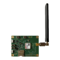
2 Interface Introduction
The interface of SIM7022 EVB is shown in the table below.
Table 5: Interface introduction
J103 is used for AT command communication,
data transmission and firmware upgrade
J104 is used for software debugging
LED101:Network status indicator light
LED102:Power status indicator light
LED103:Power-on status indicator light
SW101:Power supply switch
SW1:Firmware upgrade switch
J101 J105:Power test point
J106 J107:Module signal test point
More detailed introductions about the above functions are shown in the next section.
2.1 Power Supply
2.1.1Power Supply
SIM7022 EVB is powered by micro USB, USB plug-in connection device J103, J104 can achieve 5V power
supply effect.
The power supply block diagram of SIM7022 EVB is shown in the figure below.