SIM900 Reference Design Guide Notes
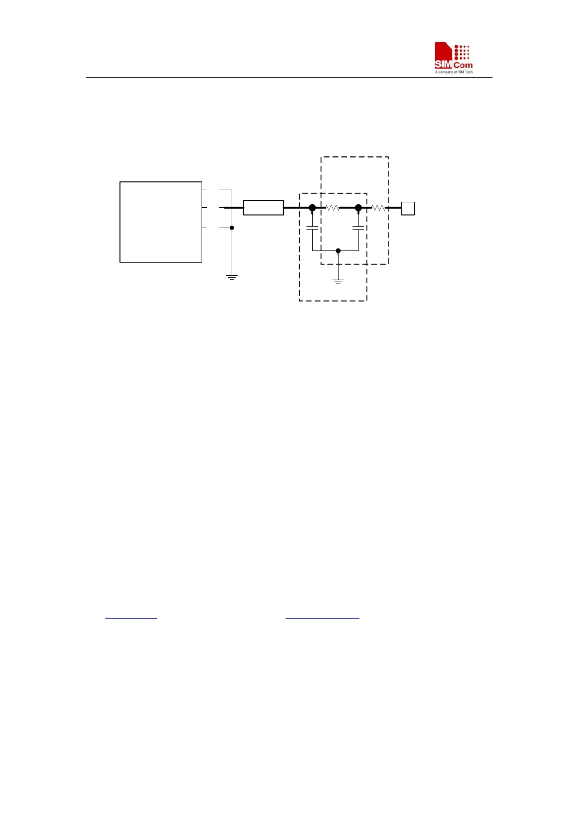
antenna matching circuit should be needed. Furthermore, to facilitate the antenna debugging and
certification testing of RF performance, we suggested the customer add a RF test connector in
series between the module’s RF port and the antenna matching circuit. The recommended antenna
matching circuit is shown as below:
R3
C6
59
SIM900
60
RF_IN
GND
C5
61
GND
R4
RF Test Port
Antenna Feed Pad
J2
J1
T-Type
matching circuit
Pi-Type
matching circuit
Figure 11: Antenna Matching Circuit
In the Figure10, the components, R4, C5 and C6 make up a pi-type matching circuit structure. If
add the optional component R3, then a T-type matching circuit structure will be made up with
another two components R4 and C5. But usually, a pi-type matching circuit is enough in antenna
tuning process. The component J2 is a RF test Port, used for conduct RF test. The traces in Bold
type must be 50 ohm impedance controlled when layout a design.
For the RF test connector, we suggested the customer use the part vended by Murata, its part
number is MM8430-2610. For detail information about this part, the customer can visit Murata’s
website: http://www.murata.com.
NOTE:For detail of RF Layout information, please to [4], SMT Module RF Design Guide.
2.6 SIM card interface
The SIM interface is powered from an internal regulator in the module. Both 1.8V and 3.0V SIM
Cards are supported. You can select the 8-pin SIM card holder. The reference circuit with 8-pin
SIM card holder illustrates as following figure.We recommend an Electro-Static discharge device
ST (www.st.com
) ESDA6V1W5 or ON SEMI (www.onsemi.com ) SMF05C for ESD protection.
The 22Ω resistor showed in the following figure should be added in series on the IO line between
the module and the SIM card for matching the impedance. The SIM peripheral circuit should close
to the SIM card socket.
The SIM_PRESENCE pin is used for detecting the SIM card. There is a 100k pull down resistor
in SIM900 module. So the R110 should not be bigger than 10K. If you don’t use the SIM card
detection function, you can let the SIM_PRESENCE pin open or connect to the GND.
SIM900_AN_Reference Design Guide_V1.01 01.27.2010
9