25
8.12 Connecting the flue
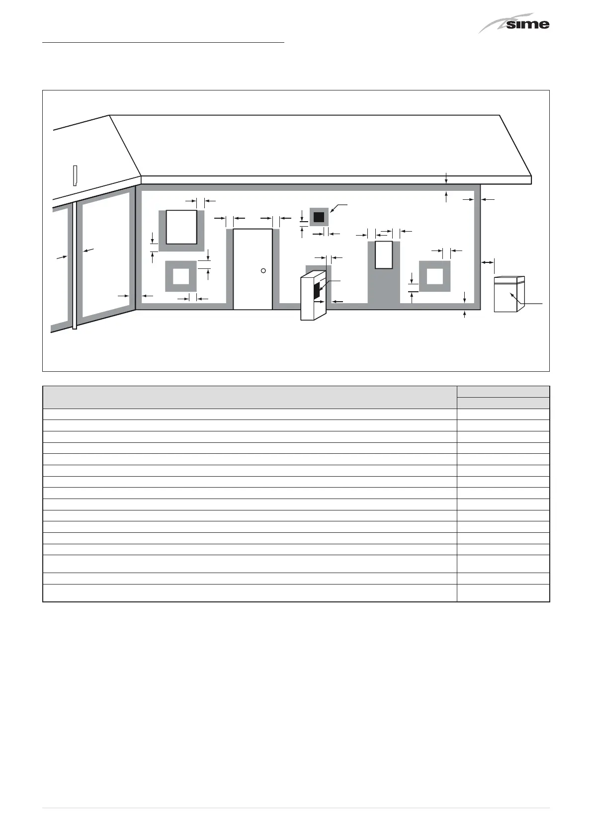
8.12.1 Flue Terminal Positions
f
c
n
k
k
j
j j
h
h
e
T
e
h
T
g
P
w
d
b
d
T
g
c
a
M
I
Door
Fig. 23
DESCRIPTION
Brava Slim HE R
Min. Clearance (mm)
Flue terminal T
Mechanical air inlet I
Gas meter M
Electricity meter of fuse box P
Shaded area indicates prohibited area
Below eaves, balconies and other projections (Appliances over 50MJ/h) a 300
From the ground, above a balcony or other surface b 300
From a return wall or external corner c 300
From a gas meter d 1000
From an electricity meter or fusebox/breaker panel e 500
From a drain pipe or soil pipe f 75
Horizontally from any building structure or obstruction facing a flue terminal g 500
From any other flue terminal, cowl or combustion air intake h 300
Horizontally from any opening window, door, non-mechanical air inlet or other opening into a building
with the exception of sub-floor ventilation
j 300
From a mechanical air inlet including a spa blower. k 1000
Vertically below an opening window, non-mechanical air inlet or any other opening into a building with
the exception of sub-floor ventilation
n 500
m
CAUTION
–
Use as a guide only. See AS/NZS5601 for flue design
details.
–
Refer to AS/NZS5601, current version, or local gas
fitting rules for specific locations.
m
CAUTION
– The location of the flue terminal must comply with
the clearances shown on this page. If you are unsure
about clearances not indicated here, in general refer
to AS/NZS 5601, or your local authority.
m
CAUTION
– All measurements are the minimum clearances
required.
– Terminals must be positioned so to avoid combustion
products entering the building.
– When the installer installs the flue through a
wall, the wall must be adequately sealed and the
hole must not affect the building structure or fire
resistance.
– Install a fire proof back board if installing on
combustible surfaces.
– The fixing method and the wall structure must be
sufficient to hold the weight of the boiler.
 Loading...