82
with the system cold, must be between 1
and 1.5 bar.
NB: The “T” versions the loading is done
by loading tap externally mounted by the
installer.
2.4.1 System draining (fig. 4)
To drain the system, turn off the boiler and
use the discharge valve (7).
2.5 INSTALLATION OF
COAXIAL DUCT
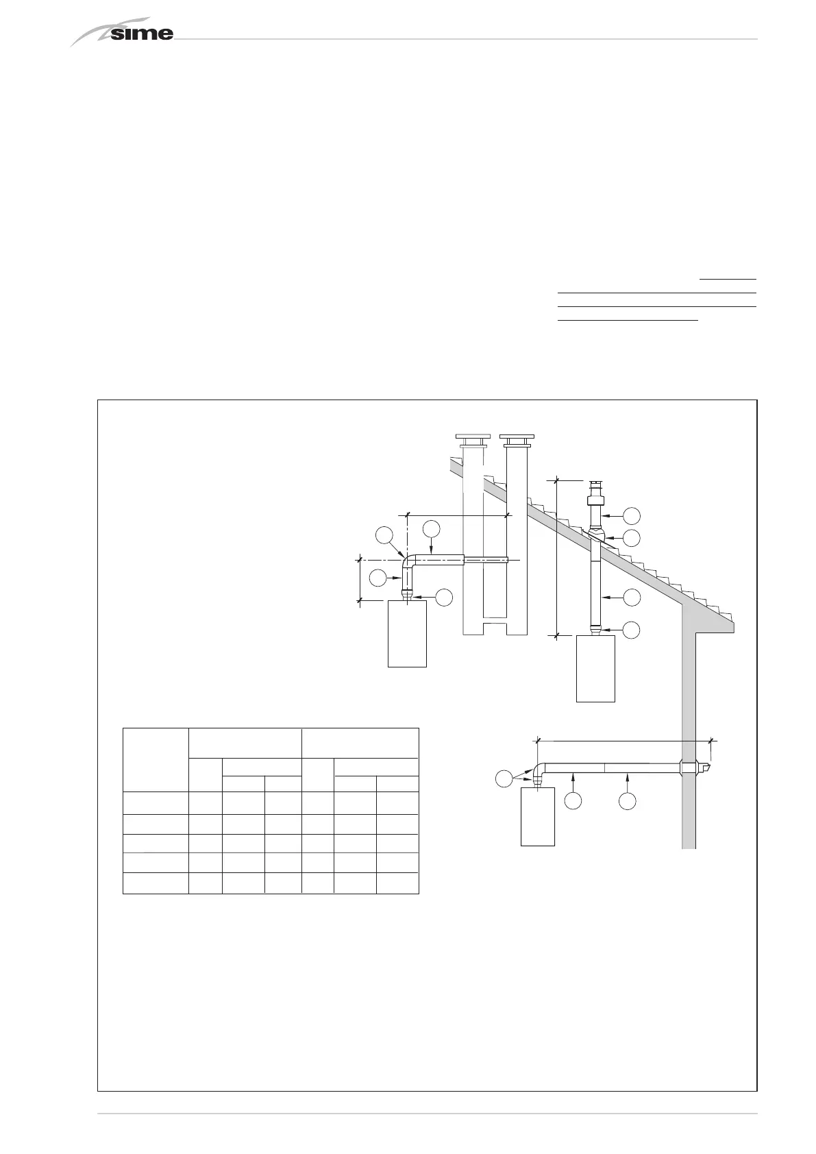
ø 60/100 - ø 80/125 (fig. 6)
The axial suction and discharge pipes are
supplied in a special kit (that can be pur-
chased separately) along with assembly
instructions.
The diagrams of fig. 6 illustrate some exam-
ples of different types of discharge modali-
ties allowed and the maximum lengths that
can be reached.
2.6 INSTALLATION OF SEPARATE
DUCTS ø 80 - ø 60 (figg. 7-8)
The kit with dedicated pipes enables to
separate the exhaust fumes pipes from the
air suction pipes (Fig. 7):
- The kit with dedicated ø 80 pipes, code.
8089912, includes a SUCTION DIAPHRAGM
THAT IS NOT used for these models. To be
able to use the air tap, cut its base with a
tool (A) and assemble it (B).
- The kits with dedicated ø 60 pipes, code
8089913, include a suction collar that
replaces the boiler collar (C).
It is now possible to insert an expansion or
bend in polypropylene without gaskets or
sealant.
The maximum overall length, resulting
from the sum of all the suction and dischar-
ge pipes, is determined by the load losses
of the single connected accessories and
should not exceed 10 mm H2O (version 12) -
15 mm H2O (version 25-30-35) (ATTENTION:
the total length of each pipe should not
exceed 25 m, even if the total loss is below
the maximum applicable loss.)
See Table 1-1/a for information on the load
losses of single accessories and the exam-
ple of Fig. 8 for information on how to calcu-
late load losses.
C33
6
5
3
2
C43
3
4
2
x
y
x + y = L (m)
H (m)
C13
1
2
1
L (m)
2
Fig. 6
IMPORTANT:
- The insertion of each additional 90°
bend with a diameter of 60/100 reduces
the available section by 1.5 meters.
- The insertion of each additional 90°
bend with a diameter of 80/125 reduces
the available section by 2 meters.
- Each additional 45° curve installed
reduces the available length by 1.0
metres.
- During assembly it is important to make
sure that the kit with axial pipes. (1) is
positioned horizontally.
NOTE
Before connecting accessories, it is
always advisable to lubricate the internal
part of the gaskets with silicon products.
Avoid using oils and greases.
Model Length of pipe Length of pipe
ø 60/100 ø 80/125
L H L H
Min Max Min Max
12 T 6 m 1.3 m 8 m 12 m 1.2 m 15 m
25 / 25 T 6 m 1.3 m 8 m 12 m 1.2 m 15 m
30 / 30 T 5 m 1.3 m 7 m 10 m 1.2 m 13 m
35 / 35 T 4 m 1.3 m 6 m 8 m 1.2 m 11 m
LIST OF ø 60/100 ACCESSORIES
1 Coaxial duct kit code 8096250
2a Extension L. 1000 code 8096150
2b Extension L. 500 code 8096151
3 Vertical extension L. 140 with coupling code 8086950
4a Additional 90° curve code 8095850
4b Additional 45° curve code 8095950
5 Tile for joint code 8091300
6 Terminal for roof exit L. 1285 code 8091205
LIST OF ø 80/125 ACCESSORIES
1 Coaxial duct kit code 8096253
2a
Extension L. 1000 code 8096171
2b Extension L. 500 code 8096170
3 Adapter for ø 80/125 code 8093150
4a Additional 90° curve code 8095870
4b
Additional 45° curve code 8095970
5 Tile for joint code 8091300
6 Terminal for roof exit L. 1285 code 8091205
 Loading...