81
ES
PT
ENG
The boiler must be installed in a fixed loca-
tion and only by specialized and qualified
firms in compliance with all instructions
contained in this manual. Furthermore, the
installation must be in accordance with cur-
rent standards and regulations.
2.1 INSTALLATION
– Boilers can be installed in all domestic
environments without any whatsoever
limit in terms of location and comburent
air supply.
– These boilers can also be installed in par-
tially covered areas, as per EN 15502, with
a maximum ambient temperature of 60°C
and a minimum ambient temperature of
-5°C. It is generally advisable to install
the boilers below weathered roofs, on the
balcony or in a protected niche, to protect
them from exposure to weathering agents
(rain, hail and snow). All boilers provide a
standard antifreeze function.
2.1.1 Anti-freeze function
The boilers are equipped with anti-freeze
function which activates the pumps and
the burner when the temperature of the
water contained inside the appliance drops
to below 6°C. The anti-freeze function is
ensured, however, only if:
- the boiler is correctly connected to the
gas and electricity supply circuits;
- the boiler is constantly fed;
- the boiler ignition is not blocked;
- the essential components of the boiler are
all in working order.
In these conditions the boiler is protected
against frost down to an environmental tem-
perature of -5°C.
ATTENTION: In the case of installation in a
place where the temperature drops below
0°C, the connection pipes must be pro-
tected.
2.2 COMPLEMENTARY ACCESSORIES
To simplify connections to the hydraulic and
gas supplies, it is also possible to use the
following accessories:
– Mounting plate, code 8081220
– Kit with bends, code 8075423
– Kit with faucets, code 8091806
– Kit with faucets boiler T, code 8091820
– Kit for the replacement of wall-mounting
assemblies of other manufacturers, code
8093900
– Solar kit for the instantaneous, code
8105101, in coupling to kit INSOL
– Mixed area kit ZONA MIX, code 8092234
– Solar kit INSOL only for heating boilers,
code 8092235
– Antifreeze heaters kit -15°C, code
8089806.
For detailed information on the assembly
of fittings, see the instructions contained
in the box.
2.3 CONNECTING UP SYSTEM
To protect the heat system from damaging
corrosion, incrustation or deposits, befo-
re installation it is extremely important to
clean the system using suitable products
such as, for example, Sentinel X300 (new
system), X400 and X800 (old system) or
Fernox cleaner F3. Complete instructions
are provided with the products but, for fur-
ther information, you may directly contact
SENTINEL PERFORMANCE SOLUTIONS LTD
or FERNOX COOKSON ELECTRONICS.
For long-term protection agains corrosion
and deposits, the use of inhibitors such as
Sentinel X100 or Fernox protector F1 is
recommended after cleaning the system. It
is important to check the concentration of
the inhibitor after each system modifica-
tion and during maintenance following the
manufacturer’s instructions (specific tests
are available at your dealer). The safety
valve drain must be connected to a collec-
tion funnel to collect any discharge during
interventions. If the heating system is on a
higher floor than the boiler, install the on/off
taps supplied in kit optional on the heating
system delivery/return pipes.
WARNING: Failure to clean the heat system
or add an adequate inhibitor invalidates the
device’s warranty.
Gas connections must be made in accordan-
ce with current standards and regulations.
When dimensioning gas pipes from the
meter to the module, both capacity volume
(consumption) in m
3
/h and gas density must
be taken into account.
The sections of the piping making up the
system must be such as to guarantee a sup-
ply of gas sufficient to cover the maximum
demand, limiting pressure loss between the
gas meter and any apparatus being used to
not greater than:
– 1.0 mbar for family II gases (natural gas);
– 2.0 mbar for family III gases (butane or
propane).
An adhesive data plate is sticked inside the
front panel; it contains all the technical data
identifying the boiler and the type of gas for
which the boiler is arranged.
2.3.1 Connection of condensation
water trap
The drip board and its water trap must be
connected to a civil drain through a pipe with
a slope of at least 5 mm per metre to ensure
drainage of condensation water.
The plastic pipes normally used for civil
drains are the only type of pipe which is
appropriate for conveying condensation to
the building’s sewer pipes.
2.3.2 Filter on the gas pipe
The gas valve is supplied ex factory with an
inlet filter, which, however, is not adequate
to entrap all the impurities in the gas or in
gas main pipes.
To prevent malfunctioning of the valve, or in
certain cases even to cut out the safety devi-
ce with which the valve is equipped, install
an adequate filter on the gas pipe.
2.4 SYSTEM FILLING (fig. 4)
Filling of the boiler and the system is done by
the system filling (11). The charge pressure,
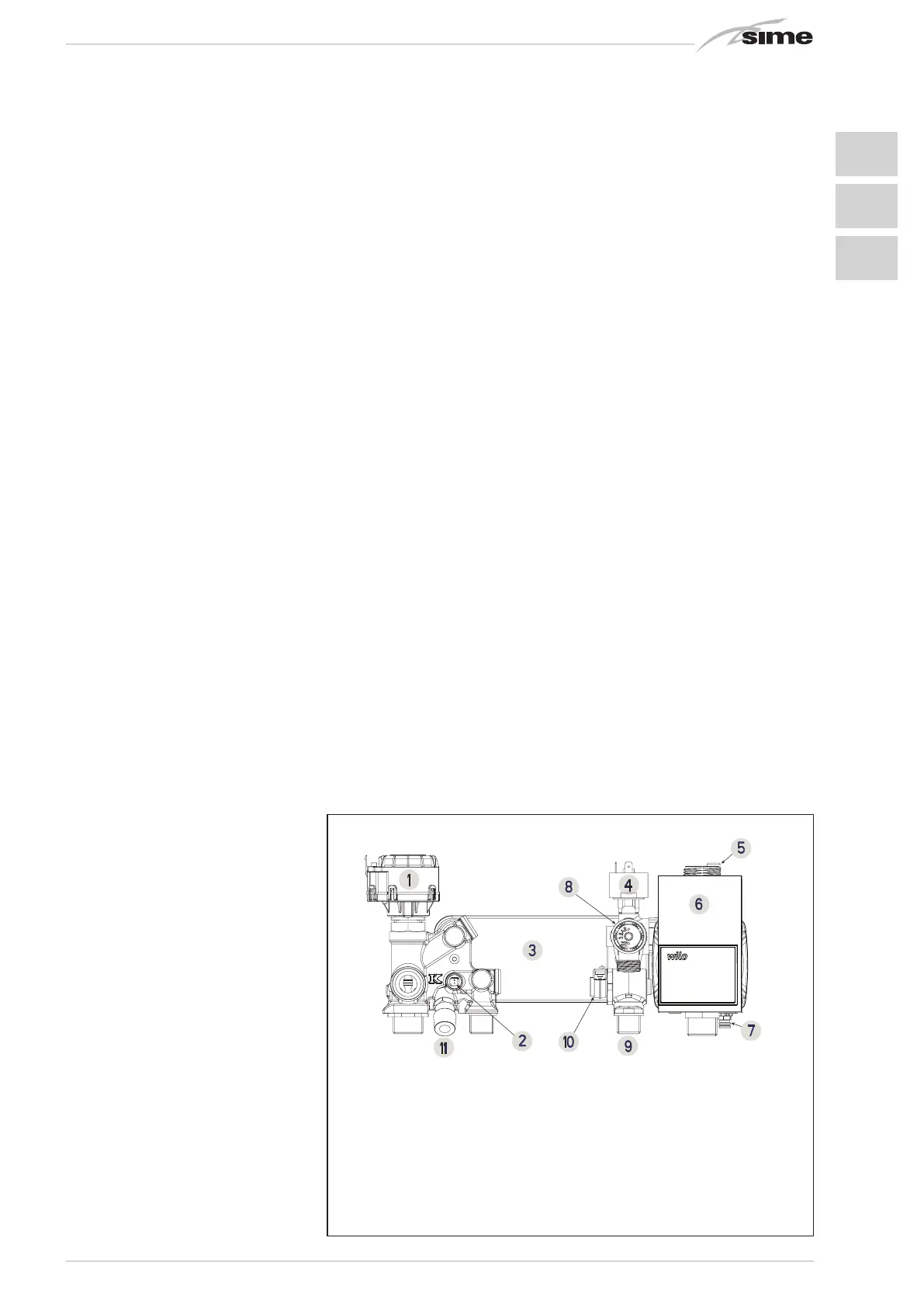
Fig. 4
2 INSTALLATION
KEY
1 Diverter valve (VD)
2 D.H.W. sensor (SS)
3 D.H.W. exchanger with plates
4 Water pressure transducer (TPA)
5 Air release vent
6 Pump high efficiency (PI)
7 Boiler discharge
8 3 BAR safety valve
9 D.H.W. filter
10 D.H.W. flowmeter sensor
11 System loading
 Loading...