2.6 “MURELLE BF” COAXIAL AIR INLET-FLUE
OUTLET ASSEMBLY
The air inlet-flue outlet assembly is supplied apart (optio-
nal) in a kit (Code 8084802). It includes:
– coaxial duct ø 60/100, length 840, with wind-proof
(anti-blowback) head already fixed to the flue dischar-
ge duct;
– pipe bend ø 60/100 with fixing screws;
– fixing clamp;
– rubber ring nut for external closing;
– sponge-rubber gasket.
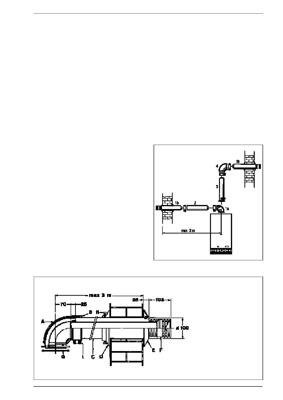
2.6.1 Assembly of the coaxial duct kit
For assembly follow closely what is indicated in Fig. 8.
– Make a hole in the wall sufficiently large to allow for
insertion of a 130 mm ø PVC pipe of the same length
as the thickness of the wall it has to pass through.
Then fix the PVC pipe in place using cement mortar.
WARNING: When cutting the pipe, remember that
the 60 mm ø flue discharge pipe must be approx.
25 mm longer than the air intake tube.
– Before sliding the pipe into the hole made in the wall,
insert the rubber sealing ring (E) into its seat made in
the tube.
– Push the tube outwards until the gasket comes out. Pull
the pipe inwards bringing the ring to rest on the wall.
– Slide the inner ring (D) and the metal collar (I) onto the
pipe.
– Push the flue discharge duct (F) fully home in the bend
and fasten the metal collar (I) in position, tightening the
two fixing screws.
– Fasten the duct (C) by tightening the two screws (H) on
the aluminium ring nut (D).
NOTE: The air intake-flue outlet assembly must slope
gently downwards to prevent rain water getting into
the boiler.
2.6.2 Coaxial air intake-flue outlet assembly
accessories
In addition to the coaxial duct kit, also the following can
be supplied on request (Fig. 9):
– Extension ø 60/100, length 855 (Code 8084800)
– Supplementary 90° pipe elbow ø 60/100 (Code
8085600)
–
Vertical extension ø 60/100, length 590 (Code 8086900).
NOTE: With the pipe bend supplied in the kit, the maxi-
mum length of piping should not exceed 3 metres. In
the case where the supplementary bend (4) is used, the
total length of piping can reach a maximum of 1.6 m.
When the vertical extension (3) is used, the terminal
part of the pipe must always come out horizontally.
8
KEY
1 Coaxial duct kit
2 Extension L. 855
3 Vertical extension L. 590
4 90° supplementary elbow
Fig. 8
Fig. 9
KEY
A Elbow flange
B Junction collar
C Outer duct
D Aluminium ring
E Rubber sealing ring
F Inner duct c/w terminal
H Fixing screw
I Protective metal collar
J Inner “O” ring