56
This occurs when the position of live
and neutral has not been respected
on the terminal block. There is a
break in the wire of the sensing
electrode or the electrode itself is
earthed: the electrode is worn out
and needs replacing.
NOTE:
Should the equipment “lock out”,
first wait at least 20 seconds from
when the warning lamp lights up,
before pressing the push-button
with built-in light; otherwise, the
appliance will not be deblocked.
3.1.2 Ionization circuit
The ionization circuit is to be checked
using a dial-type micro-ammeter, or
preferably a digital micro-ammeter
with a 0 to 50 µA scale.
The micro-ammeter terminals must be
series-connected to the wire of the
sensing electrode.
Under normal operating conditions,
the value oscillates between 6÷12 µA.
The minimum value of the ionization
current for which the equipment can
“lock out” is about 1 µA.
In this case, make sure that there is a
good electrical contact and check the
degree of wear of the end part of the
electrode and the corresponding cera-
mic protection.
3.2 REGULATION THERMOSTAT
“RS” boilers are equipped with a regu-
lating thermostat with a double con-
tact having differentiated setting. This
makes it possible to obtain a reduction
of heat output before the burner goes
out completely, by means of the coil
assembly (fig. 20) installed on the gas
valve regulator.
This step-modulation system affords
the following advantages:
– higher overall boiler efficiency;
– containment within acceptable
values of the increase in temperatu-
re that takes place in the cast-iron
body (heat inertia) when the burner
goes out.
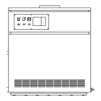
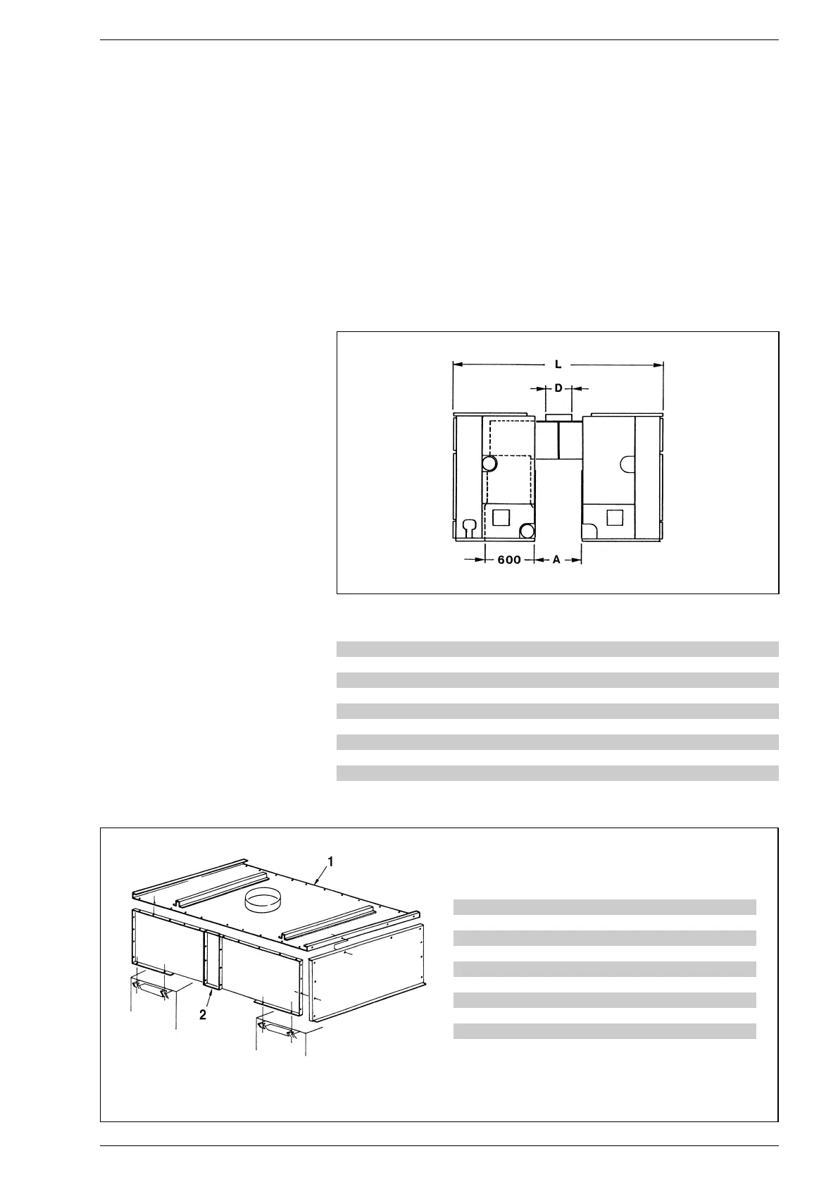
3.3 LAYOUT WITH TWO
OPPOSED BOILERS
Accessories are available on request
to permit an opposed layout of two boi-
lers which will reduce overall dimen-
sions and facilitate connection with the
flue through a single flue gas duct (figu-
res 14 - 15).
Table 2
gives the dimensions of the
two boilers combined and the diameter
of the chimney.
Fig. 14
TABLE 2
D (ø mm) L (mm) A (mm)
RS 6 400 2360 600
RS 7 400 2360 600
RS 8 400 2360 600
RS 9 400 2360 600
RS 10 450 2360 600
RS 11 450 2360 600
RS 12 500 2380 620
RS 13 500 2380 620
RS 14 500 2380 620
Connecting cover Connecting panel
RS 6 6136208 6136251
RS 7 6136209 6136251
RS 8 6136210 6136251
RS 9 6136211 6136251
RS 10 6136212 6136252
RS 11 6136213 6136252
RS 12 6136205 –
RS 13 6136206 –
RS 14 6136207 –
Fig. 15
KEY
1 Connecting cover
2 Connecting panel
 Loading...