control board through connections to
terminals 1-2.
Make sure that live and neutral corre-
spond to the wiring diagram given
below; otherwise, the flame detection
circuit will remain inactive, and the
equipment will “lock out”. Electric power
supply must be 230 V - 50 Hz single-
phase through a main switch protected
by a 3 A fuse (fig. 13), with at least 3 mm
spacing between contacts.
NOTE: Device must be connected to
an efficient earthing system. SIME
declines all responsibility for injury or
damage to persons, animals or
things, resulting from the failure to
provide for proper earthing of the
appliance. Always turn off the power
supply before doing any work on the
electrical panel.
55
3.1 ELECTRONIC IGNITION
The “RS” version boilers are of the
type with automatic ignition (without
pilot burner). They are therefore equip-
ped with the SM 191.1 electronic con-
trol and protection programmer with
built-in transformer.
Ignition and flame detection is control-
led by two electrodes located at the
end the burner. Ignition occurs directly
on the burner. Maximum safety is in
any case guaranteed, with intervention
times, for accidental switching off or
gas failure, of within two seconds.
3.1.1 Operating cycle
Before igniting the boiler, use a voltme-
ter to make sure that the electrical
connection to the terminal block has
been made properly, respecting the
position of live and neutral, as shown in
the diagram. Then press the switch on
the control panel. The boiler is now
ready to start working; a discharge
current is sent to the ignition electrode
through the SM 191.1 programmer,
and the gas valve opens at the same
time. Burner ignition normally takes
place within 1 or 2 seconds. However,
it is possible for ignition failures to
occur, with consequent activation of
signal indicating that the equipment
has “locked out”. Failures may be due
to one of the following causes:
– Gas failure
The appliance runs through the cycle
normally sending electric power to
the ignition electrode. The electrode
continues spark discharge for a maxi-
mum of 8 sec. If the burner does not
ignite, the equipment “locks out”.
This may occur upon first ignition or
after long periods of boiler lay-off
when there is air in the pipes. It may
be caused by the failure of the gas
valve to open owing to a break in the
electric coil.
– Ignition electrode fails to spark
In the boiler, only opening of gas to
the burner is seen to occur. After 8
sec. the equipment “locks out”.
This may be due to there being a
break in the wire of the electrode or
the wire not being properly fastened
to the terminal 10; or else, the tran-
sformer has burnt out.
– No detection of flame
The continuous spark discharge of
the electrode is noted starting from
ignition even though the burner is lit.
After 8 seconds have elapsed, the
sparks cease, the burner goes out,
and the warning lamp indicating
equipment “lock-out” lights up.
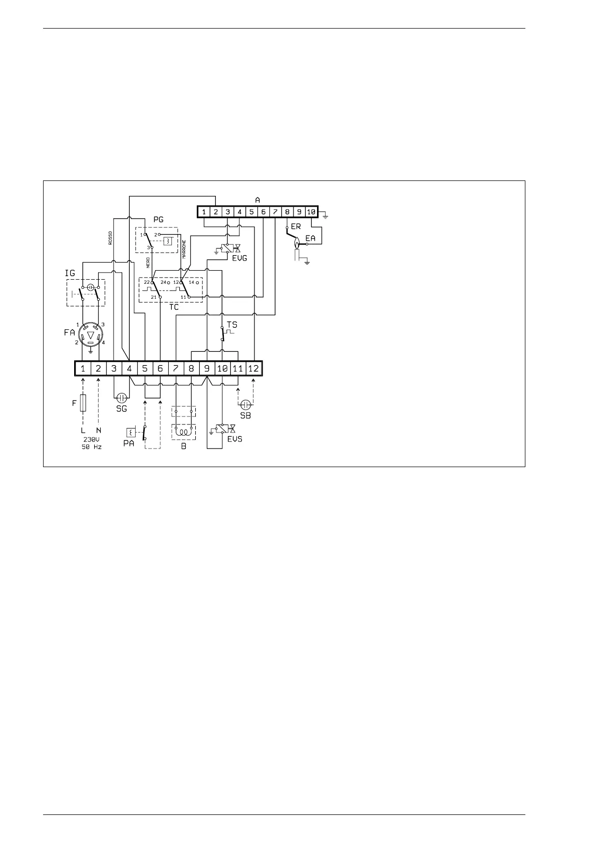
KEY
SB External “lock-out” signal (not supplied)
PG Gas pressure switch
EVG Main gas valve
F 3 AF fuse (not supplied)
ER Sensing electrode
EA Ignition electrode
L Live
N Neutral
TC Step-regulation thermostat
IG Main switch
SG Gas pressure warning light
TS Safety thermostat
A SM 191.1 programmer
PA Water pressure switch (not supplied)
B Pressure adjusting coil
EVS Second gas solenoid valve
FA EMC filter
Fig. 13
3 CHARACTERISTICS
 Loading...