53
2.8 ASSEMBLY OF BURNER
MANIFOLD
The burner manifold is supplied sepa-
rate, in the packaging containing the
smoke chamber and the outer casing.
To fasten the manifold to the cast-iron
body, use the four screws TE M8 x 16,
which must be screwed onto the
threaded lugs on the two heads of the
boiler body (fig. 7).
2.9 ASSEMBLY OF
GAS-CONNECTION PIPE
Once you have chosen on which side to
attach the gas unit, assemble the flange
with connecting pipe, fastening it with
the screws TE M12 x 25 supplied (fig. 8).
NOTE: After assembling all the gas
connections, a test for gas tightness
must be carried out using soapy
water or special products. DO NOT
USE NAKED FLAMES.
2.10 ASSEMBLY OF BURNERS
Once the burner manifold has been
fastened to the boiler body, slide the
burners into the combustion chamber
one by one, making sure that the burner
slits are turned upwards. Push the bur-
ner to the other end of the combustion
chamber, so that the burner support sli-
des into the hole made in the cast-iron
wall that separates one section from
the next (fig. 9). Fasten the burner to
the manifold with a screw TCB M5 x 8.
2.11 ASSEMBLY OF OUTER CASING
To assemble the outer casing, proceed
as follows (fig. 10):
– position the front and rear supports
(1) of the casing base between the
feet of the two heads;
– fasten the two side supports (2) and
(3) to the front and rear parts (1) of
the casing base, using the M6 nuts
provided;
– fasten the panel (4) to the panel (5),
and the panel (7) to the panel (8),
using the slot pins;
– fasten the panels (4) and (5) to the
panel (6), and the panels (7) and (8)
to the panel (9) by means of the
pressure pins, making sure that
they are joined together, using the
two self-tapping flathead screws
7SP x 1/2” provided;
– assemble the panels (4) and (6) on
the base (3), fastening them on the
slot pins. Repeat the same opera-
tion to fasten the panels (7) and (9)
to the base (2);
– position the lower front wall (11), sli-
ding it between the screws that are
located on the brackets of the bur-
ner manifold support and the cast-
iron body. Fasten the wall to the
panels (6) and (9) with two self-tap-
ping flathead screws 7SP x 1/2”;
–
position the upper front wall (12),
fastening it to the panels (5) and (8)
and to the wall (11), using four self-
tapping flathead screws 7SP x 1/2”;
– fasten the rear wall (13) to the
panels (4)-(5) and (7)-(8), using the
eight self-tapping flathead screws
7SP x 1/2” provided;
– assemble the front base strip (14),
fastening it to the panels (6) and (9),
using the pressure pins;
– proceed as above to fasten the
upper front panel (16);
– assemble the cover (10);
–
before assembling the door (15),
pass the capillary tubes of the ther-
mostats and the thermometer (5 fig.
12) through the hole on the side (9).
CAUTION: Before inserting the bulbs
of the instruments in the sheath,
check their position to make sure that
the bulb of the regulating thermostat
is inserted first and pushed in until it
touches the bottom of the sheath.
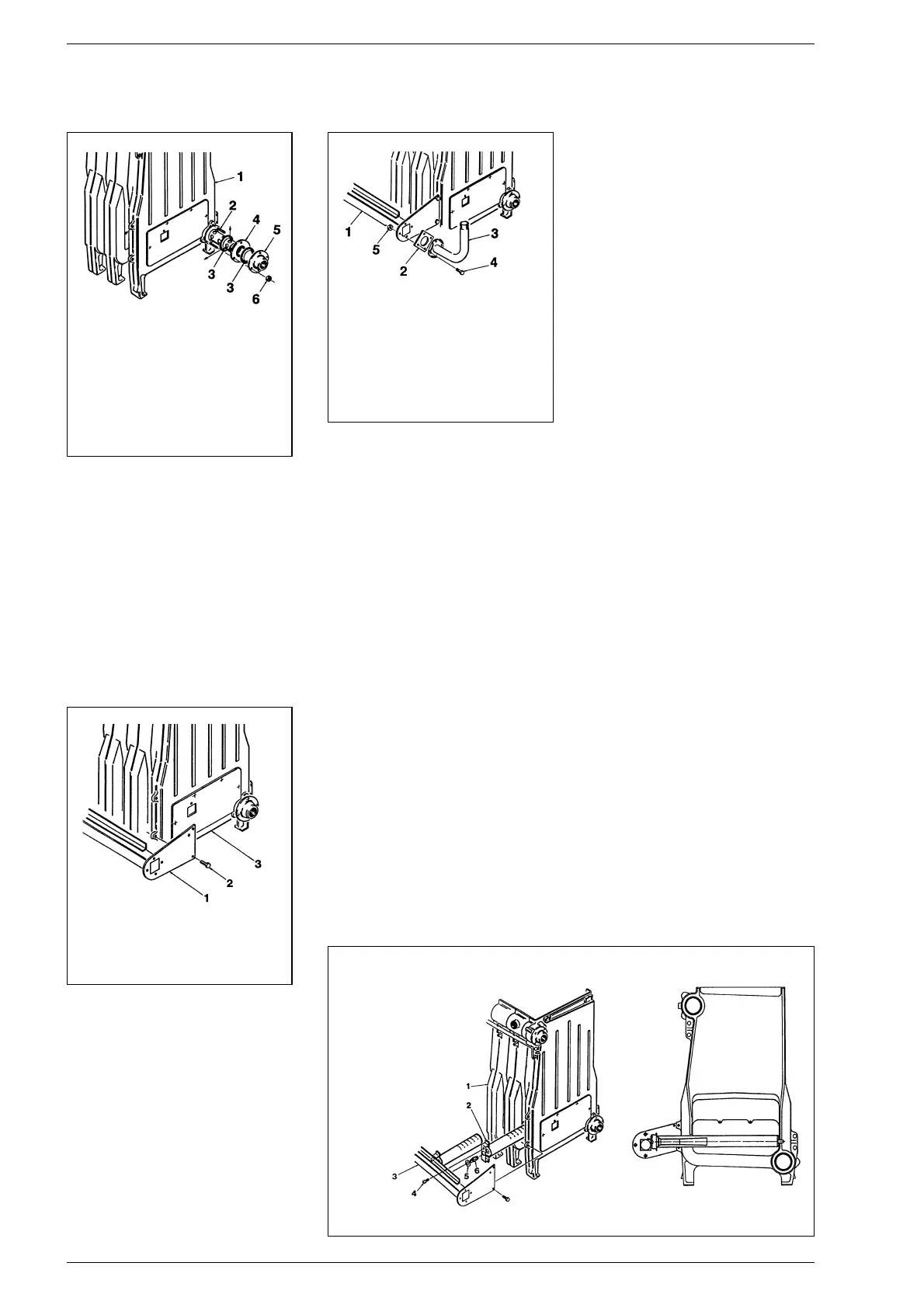
KEY
1 Boiler body
2 Stud bolt M12 x 60
3 Gasket ø 65/95 x 2
4 Distributor pipe
5 Collar flange DN50 2”
6 Nut M12
Fig. 6
KEY
1 Burner manifold
2 Screw TE M8 x 16
3 R.H. head
Fig. 7
KEY
1 Burner manifold
2 Rubber gasket
3 Flanged pipe
4 Screw TE M12 x 25
5 Nut M12
Fig. 8
KEY
1 Boiler body
2 Burner
3 Burner manifold
4 Screw TCB M5 x 8
5 Aluminium
washer ø 14
6 Burner nozzle
Fig. 9
 Loading...