The boiler should be installed in a fixed
location and shall be carried out only by
specialized and qualified firms in com-
pliance with all instructions contained
in this manual.
2.1 BOILER ROOM
AND VENTILATION
There are no particular regulations to
follow with reference to the boiler
room because “RX 19-26” boilers,
which do not exceed the 35 kW limit,
can be installed in rooms that are suf-
ficiently ventilated.
The rooms where the gas-fired
systems are installed must receive at
least the quantity of air necessary for
the normal combustion of the gas used
by the various installations.
Therefore, to ensure the air circulation
in the rooms, it is necessary to make
some holes in the walls.
These holes must have the following
characteristics:
– Have e total free surface of mini-
mum 6 cm
2
for each kW of thermal
capacity, for a minimum of 100 cm
2
.
–
They must be located as close as
possible to floor level, not prone to
obstruction and protected by a
grid which does not reduce the
effective section required for the
passage of air.
The “RX 37÷55” models with a capa-
city exceeding 35 kW shall instead be
installed in a boiler room that meets
the existing safety regulations for
network gas-fired heating systems,
where minimum distances must be
observed.
2.2 BOILER CONNECTION
Before connecting the boiler circulate
some water in the pipes to eliminate
any foreign bodies which may prevent
the equipment from working properly.
When making the hydraulic connec-
tions, follow the instructions of fig. 1
carefully.
Connections shall be easily disconnec-
ted by means of unions with revolving
fittings. It is always advisable to mount
suitable interception gate valves on the
C.H. flow and C.H. return plant pipes.
The gas connection must be made
43
GR
RO
RUS
SCG
IT
ES
PT
GB
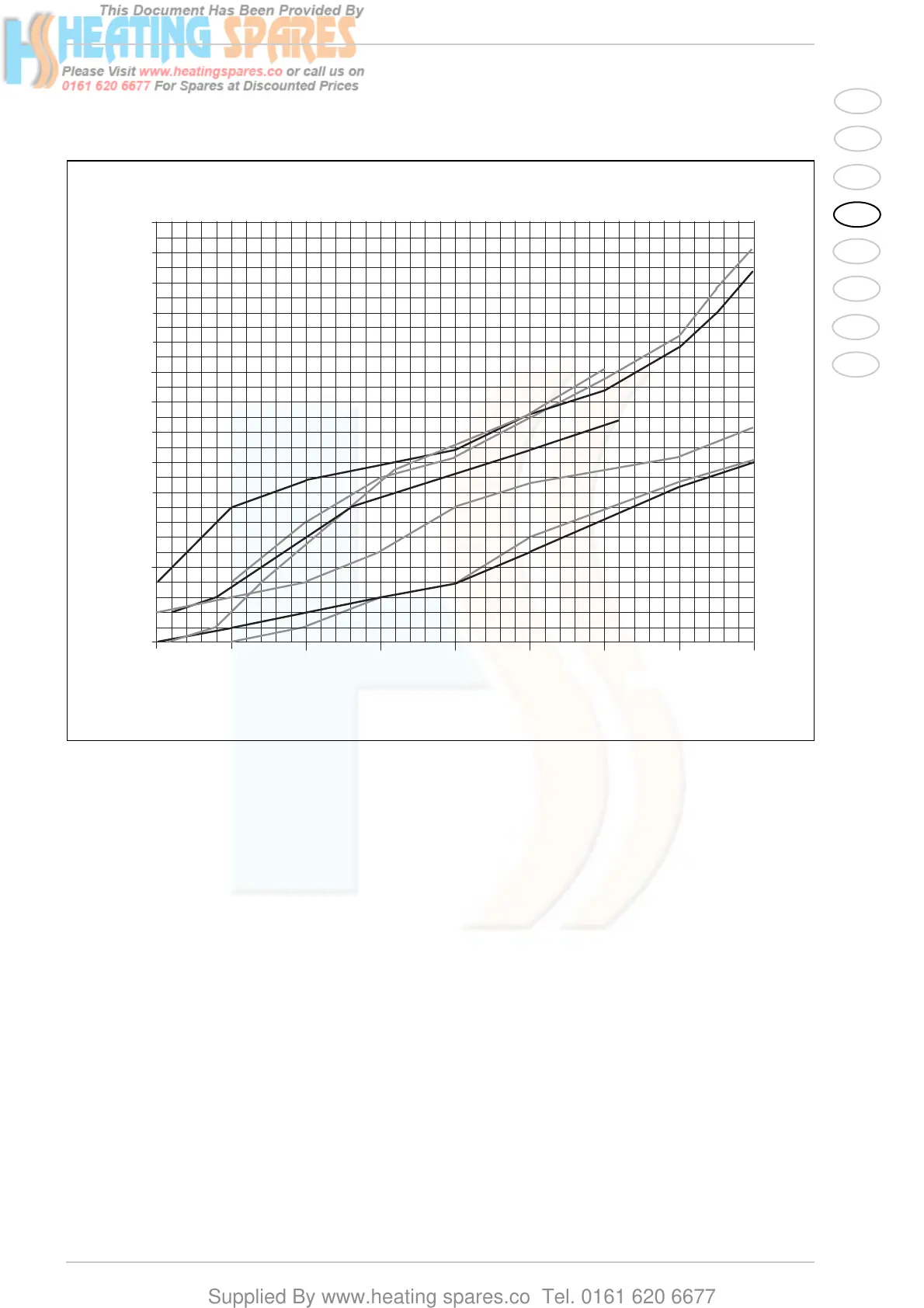
1.5 BOILER CIRCUIT LOAD LOSS
Fig. 2/a
 Loading...