The boiler should be installed in a fixed location and shall
be carried out only by specialized and qualified firms in
compliance with all instructions contained in this manual.
2.1 BOILER ROOM
There are no particular regulations to follow with referen-
ce to the boiler room because “RX 19-26” boilers, which
do not exceed the 35 kW limit, can be installed in rooms
that are sufficiently ventilated.
The “RX 37÷55” models with a capacity exceeding 35 kW
shall instead be installed in a boiler room that meets the
existing safety regulations for network gas-fired heating
systems, where minimum distances must be observed.
2.2 VENTILATION REQUIREMENTS
The rooms where the gas-fired systems are installed must
receive at least the quantity of air necessary for the nor-
mal combustion of the gas used by the various installa-
tions. Therefore, to ensure the air circulation in the rooms,
it is necessary to make some holes in the walls. These
holes must have the following characteristics:
− have e total free surface of minimum 6 cm
2
for each kW
of thermal capacity, for a minimum of 150 cm
2
(if
necessary, these holes can be obtained by increasing
the space between the door and the floor).
− be on the lower part of an external wall, preferably
facing the one with the burnt gas discharge.
2.3 BOILER CONNECTION
Before connecting the boiler circulate some water in the
pipes to eliminate any foreign bodies which may prevent
the equipment from working properly. When making the
hydraulic connections, follow the instructions of fig. 1
and 2 carefully. The boiler connections shall be made by
using rigid pipe fittings or steel flexible pipes that do not
cause any stress on the installation.
Connections shall be easily disconnected by means of
unions with revolving fittings. It is always advisable to
mount suitable interception gate valves on the C.H. flow
and C.H. return plant pipes.
The gas pipe connection shall be made with weldless
galvanized steel pipes (Mannesmann type) with threa-
ded and lined joints, and using three-piece pipe fittings
only for initial and end connections. Pipes inside walls
shall be covered by a suitable sheath. The size of gas
pipes from the meter to the boiler will depend on both
the volume capacity (consumption) expressed in m
3
/h
and the gas density.
The installation pipe sections must be such as to ensu-
re the supply of the quantity of gas necessary to meet
the maximum requirements, keeping the loss of pressu-
re between the meter and any equipment. The door car-
ries on the inside an adhesive plate with the technical
specifications and the type of gas suitable for the boiler.
2.4 FLUE CONNECTION
A flue for the discharge into the atmosphere of the pro-
ducts of combustion of natural draught plants must have
the following characteristics:
− be sealed against the products of combustion, water-
proof and insulated;
− be made of materials capable of withstanding normal
mechanical stresses, heat and the action of the pro-
ducts of combustion and their condensate;
− be vertical and with no narrowing throughout its whole
length;
− be properly insulated to avoid flue gases condensing
or cooling, especially if it is placed outside a building
or in rooms with no heating;
− be kept at a safe distance from combustible and
easily inflammable materials by an air space or any
other suitable insulating material;
− have a chamber collecting solid materials and con-
densates below the mouth of the first flue; this cham-
ber must be at least 500 mm high.
Access to this chamber must be ensured through a
hole with an airtight metal door;
− its inner section must be round, square or rectangular;
if it is square of rectangular, the corners must be
round and have a radius of 20 mm minimum; however,
hydraulically equivalent sections are also permitted;
− be topped by a chimneypot having its outlet outside
the reflux area in order to avoid back pressures which
may obstruct the free discharge of flue gas into the air;
− there must be no mechanical suction equipment at the
top of the pipe;
− there must be no overpressure in stacks placed insi-
de or adjacent to inhabited rooms.
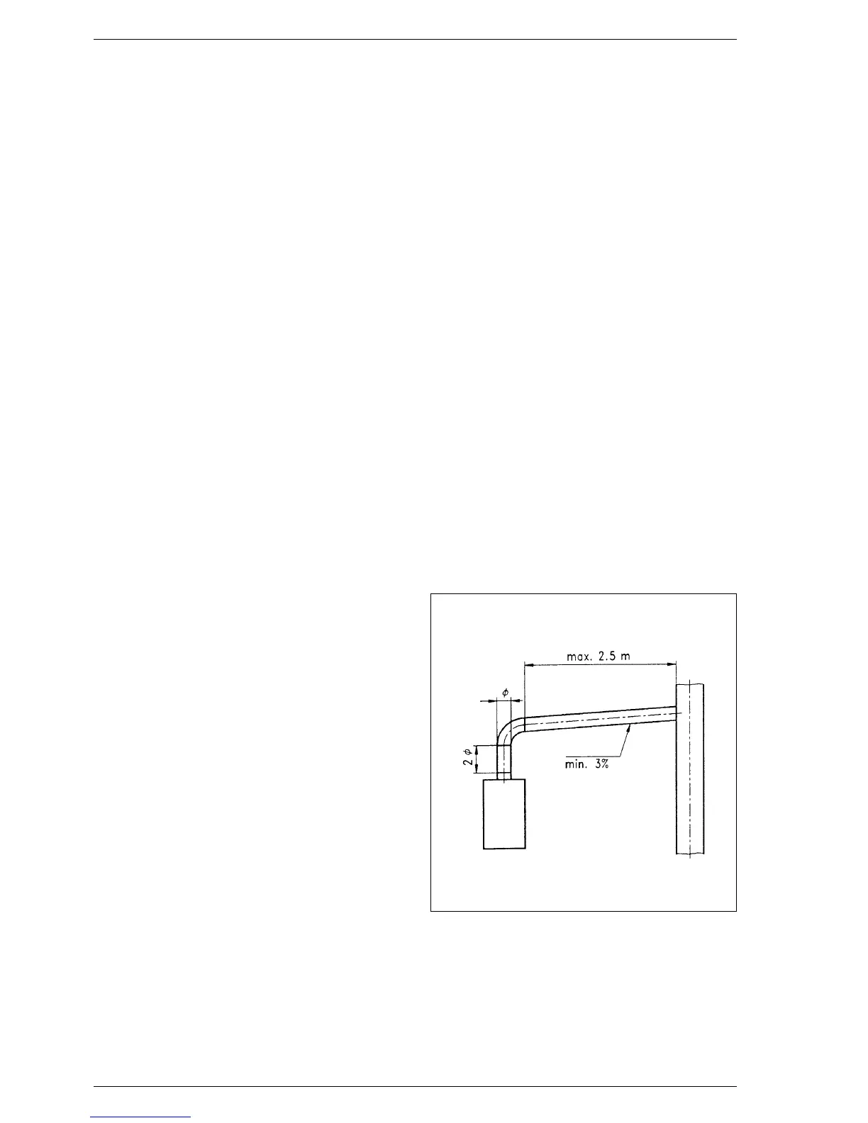
Fig. 6 refers to the boiler connection to the flue or to the
stack through flue ducts. In making the connection
observe the dimensions given and use sealing materials
capable of withstanding mechanical stresses and flue
heat over time. At any point of the flue the burnt gas tem-
perature shall not exceed the dew point temperature.
Maximum three changes of direction can be made, inclu-
ding the union to the stack/flue. For changes of direction,
use only curved components.
5
2 General instructions for the installation
Fig. 6
Gradient