2.8 OVERHEAT PROTECTION
In case the boiler temperature exceeds 100°C an
overheat stat, connected in the thermocouple circuit, will
extinguish the pilot burner thus shutting off the gas flow to
the pilot and main burner.
On the “RX CE” models the overheat stat is supported by
a bracket fixed to the gas valve flange (6-14 fig. 5).
On the “RX CE IONO” models the overheat stat is loca-
ted on the control board and is connected in series with
the smoke stat.
“RX 19-26” models are equipped with overheat thermo-
stat with automatic resetting, and “RX 37÷55” with
manual resetting.
Should the thermostat with manual resetting trip off, it will
be necessary to unscrew the cover and reset the button
below for the pilot burner to restart.
To restart the boiler it will be necessary to wait for the tem-
perature inside the exchanger to go below the overheat
stat set value.
2.9 SMOKE SAFETY DEVICE
The smoke thermostat on the control panel (3 fig. 5) is
standard on “RX CE” boilers. It provides a protection
against the discharge of flue gas into the atmophere. This
control device stops the gas valve if the flue gas is
descharged into the boiler room is continuous way and
in such quantities as to become dangerous. To start the
boiler again, switch off the power, then remove the smoke
stat cover and reset the button below. If the thermostat
continues to trip off, it will be necessary to check the flue
thoroughly, making all the necessary changes to ensure it
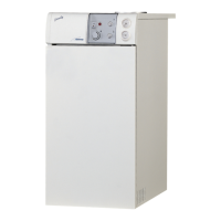
works properly. On the “RX 37÷55” models, the smoke
stat capillary on the back of the boiler shall be put into the
12.5 Ø hole of the droughtdiverter support bracket and
fixed to it with the fitting and the M 12 lock nut already
mounted on the capillary (fig. 8).
NOTE: It absolutely forbidden, under penalty of war-
ranty loss, to disconnect, remove or tamper
with safety devices. Please contact the autho-
rized technical personel if controls or replace-
ments of the devices are needed.
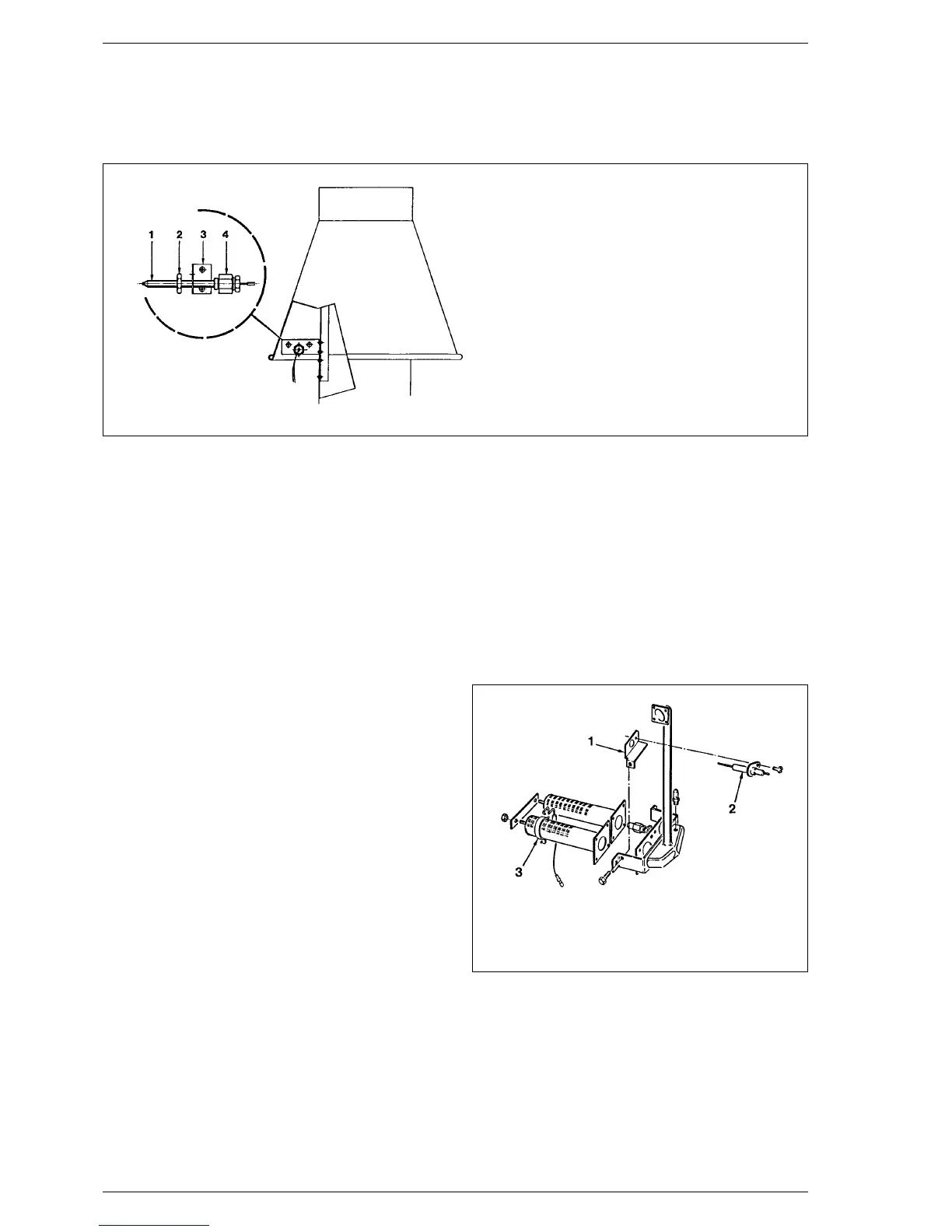
2.10 ELECTRONIC IGNITION
The “RX CE IONO” boilers are equipped with electronic
ignition without pilot flame; they are therefore equipped with
an electric control and protection device. An electronic pro-
grammer, model Brahma FM 11, controls the ignition and
the ionisation by means of two electrodes as shown in fig. 9.
Maximum safety is garanteed because in case of acciden-
tal extinction of the burner the gas flow is stopped within 1
second. A reference mark made on the burner ensures the
proper application of the ignition electrode.
2.10.1 Working cycle
Before lighting the boiler check with a voltmeter that the
electric connection to the terminal board has been pro-
perly made observing the phase and neutral positions of
the wiring diagram. Press the main switch on the control
board; the lamp will light if there is power. At this stage
the boiler will start to work sending, via the FM 11 pro-
grammer, a discharge current to the electrode and, at the
same time, opening the gas valve. Normally the burner
takes 1 or 2 seconds to light.
7
KEY
1 Ionisation electrode support
2 Ionisation electrode
3 Ignition electrode
KEY
1 Smoke stat capillary
2 M12 lock nut
3 Capillary support bracket
4 M12 fitting
Fig. 9
Fig. 8